Franklin Fueling Systems TSP-LL2 User Manual
Page 6
6
Above Riser Probes
For above-riser probes or ASTs, install the stainless steel
TSP-K4AS riser adapter by tightening the lower swage
lock fitting. (Figure 6)
Figure 6: TSP-K4AS cap with Swage-Lock Fitting
Slide the floats onto the probe shaft after the probe has
been inserted through the cap. Refer to manual 000-0113,
TSP-K4AS with TSP-UVPK Installation Instructions for more
information about mounting probes above the riser cap.
Recording Probe Information:
Gradient, Model # and Serial Number
For each tank, record the probe model number, serial
number, and the probe gradient value (propagation
constant), The TS-LL2 has two labels. The label included
with the splice kit in the shipping tube contains the same
information that is on the probe head label:
• Model (TSP-LL2-X)
• Serial #
• Gradient
• Probe length
• Max. Tank size
• Temperature sensor locations
For every installed probe, use indelible ink pen and
mark the tank number where it was installed on each
label. Save labels and make sure they are kept near
the tank monitor for correct programming.
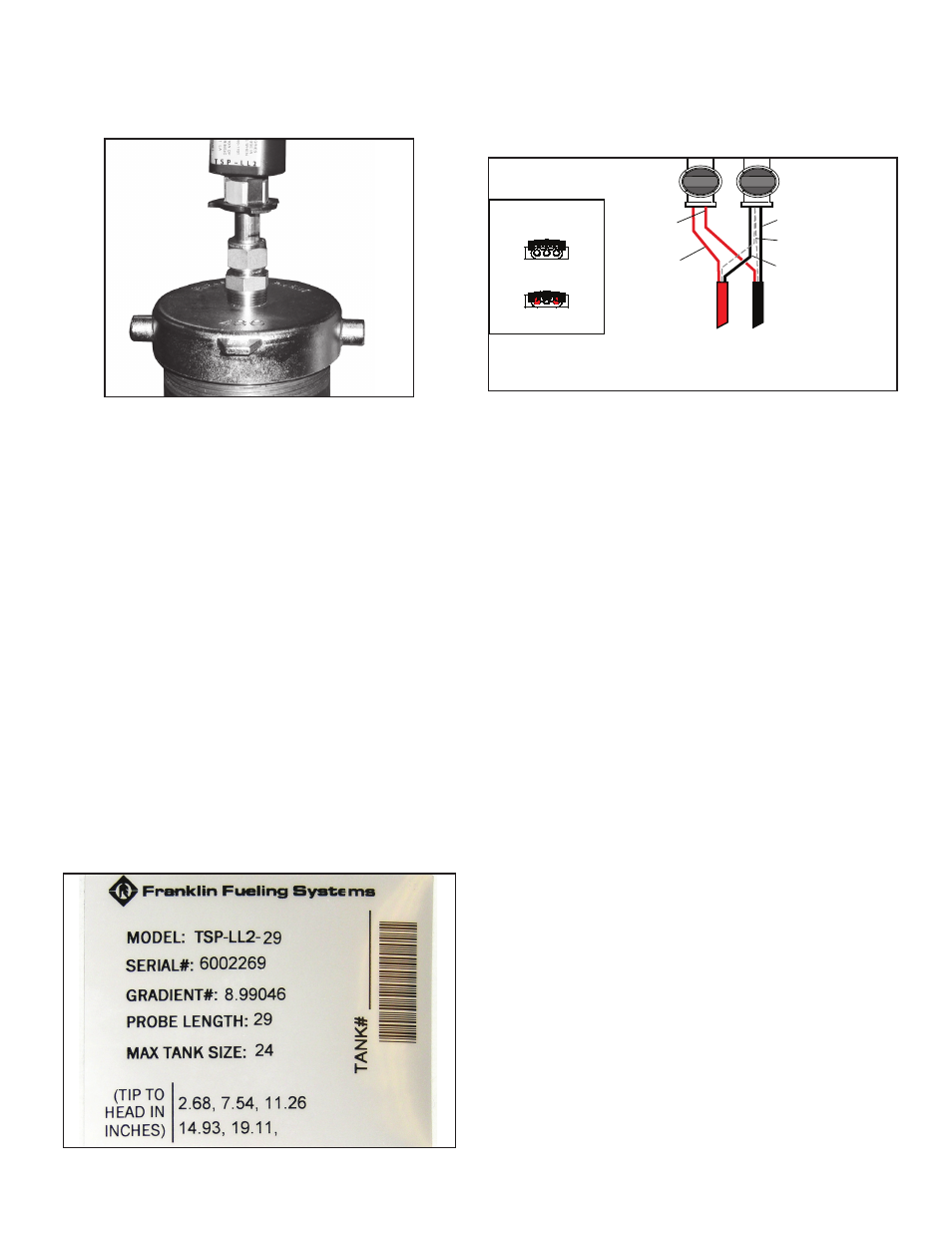
Figure 7: Sample Probe Information Label
Probe Wiring
LL2 Probe Splice Kit – Installation Instructions
The Liquid Level Probe Splice Kit includes 2 Electrical
Connectors for installation inside the manhole junction box
only. It is not intended for direct burial applications.
After Crimp
To
Console
To
Probe
Before Crimp
End view of splice
Black wire of probe
Both shield wires
Red wire of
field cable
Black wire of
field cable
Red wire
of probe
Connect bare metal shielding together
Figure 8: Splice Kit for Probe Wiring
1. Use 2 moisture-resistant connectors (provided) for
each probe installation.
2. Insert 2 red unstripped wires into two separate
openings of the first connector.
Make sure the
wires are fully inserted and seated at the end of
the connector
.
Note: Belden cable # 89182 (for runs longer than 400
feet) has a yellow wire. Wire the YEL wire to the
+ (RED) probe terminal inside the console.
3. Insert 2 black unstripped wires into two separate
openings of the second connector and then insert
the 2 shield wires into the remaining opening of the
second connector.
Make sure the wires are fully
inserted and seated at the end of the connector
.
4. The white wire inside the yellow probe cable is not
used. Do not insert it into any connector. Cut the
white wire back flush to the jacket of the yellow
probe cable.
5. Use 8” slip-joint pliers and squeeze each
connector together (position the plier’s jaws on
the connector perpendicular to the wires and drive
the black cap down almost flush to the edge of the
connector body).
For a supply of moisture-resistant splice connectors,
Order:
• TSPKW30 for a pack of 30 splices.
For direct burial cable applications or for applications that
don’t use a junction box, order:
• TSP-DB1 for a single kit
• TSP-DB10 for 10 kits.
For information about direct-burial applications, refer
to manual 000-1041, Direct Burial Cable Installation
Instructions and 000-1133, Direct Burial Splice Kit
Installation Guide.