Cabling the cable cubby aap devices – Extron Electronics RGB 580xi User Guide User Manual
Page 18
c
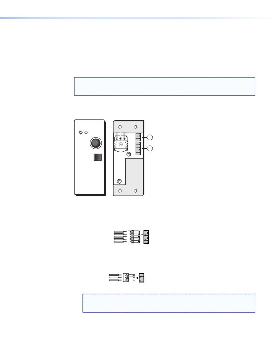
Input select button — Pressing this button results in contact closure between pins A
and B of the contact closure control connector on the front panel of the RGB 580xi.
Cabling the Cable Cubby AAP Devices
Various Extron CC AAP devices for the RGB 580xi come with rear panel connectors that may
require cabling.
NOTE: Although the control cable/LED cable assembly comes prewired to the captive
screw connectors, any subsequent connector replacement will require the
following cabling instructions.
To cable the captive screw connectors, refer to the following diagrams and position the wires
according to the view angle of the captive screws.
RGB 580xi CCSI AAP
J4
J2
1
2
INPUT
SELECT
HORIZONTAL
SHIFT
a
Control connector (J4) — Insert wires into and tighten the screws on the 3.5 mm,
5-pole captive screw connector. This connector is used for contact closure and horizontal
shifting signals. Wire the connector as shown in the following illustration.
Control One-Piece Captive Screw Conn 2.eps
Horizontal shift
+
(green)
Horizontal shift ground (gray)
Horizontal shift
–
(brown)
Contact closure
+
(light blue)
Contact closure
–
(purple)
Cont
ro
l
RGB 580xi AAP control wiring
1
2
3
4
5
b
LED connector (J2) — Insert wires into and tighten the screws on the 3.5 mm, 3-pole
captive screw connector. This connector is used for powering the green and amber LEDs.
Wire the connector as shown in the following illustration.
RGB 580xi AAP LED 2-piece wiring
Green LED (pink)
LED ground (yellow)
Amber LED (orange)
LED
1
2
3
NOTE: The VGA and audio cable assemblies are routed through the Cable Cubby.
Refer to the Cable Cubby User’s Manual for Cable Cubby installation
instructions.
RGB 580xi • Installation and Operation
14