Cabling the aap device rear connectors, Figure 8. example of aap device rear connectors, Example of aap device rear connectors – Extron Electronics RGB 580xi User Guide User Manual
Page 16: Control one-piece captive screw conn 2.eps, Audio two-piece captive screw conn2.eps
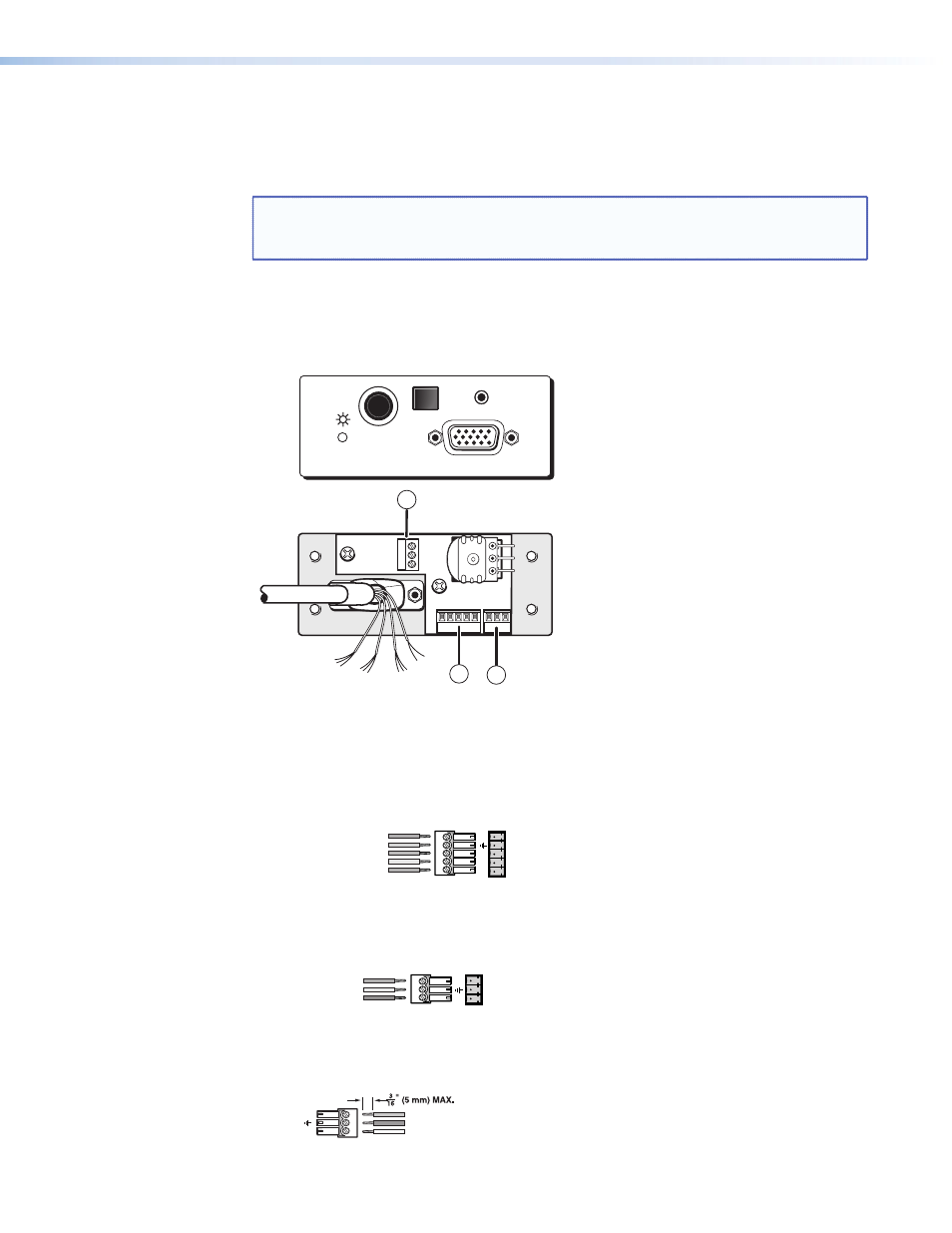
Cabling the AAP Device Rear Connectors
Various Extron AAP devices for the RGB 580xi may come with several rear connectors that
require cabling.
NOTE: Although the VGA and control cable/LED assembly comes prewired to the
captive screw connectors, any subsequent cable assembly replacement will
require the following cabling instructions.
To cable the captive screw connectors, refer to the following diagrams and position the wires
according to the view angle of the captive screws. When using the Extron VGA and control
cable assembly (see
“Optional RGB 580xi AAP Replacement Cables”
for part numbers),
refer to the color of each wire for signal identification.
1
3
Example of AAP device rear connectors
2
Red
Black
White
Yellow
Pink
Orange
Green
Gray
Brown
Lt. Blue
Purple
SHIFT
COMPUTER IN
SELECT
AUDIO IN
RGB 580xi
Figure 8.
Example of AAP Device Rear Connectors
a
Control connector (J4) — Insert wires into and tighten the screws on the 3.5 mm,
5-pole captive screw connector. This connector is used for contact closure and horizontal
shifting signals. Wire the connector as shown in the following illustration.
Control One-Piece Captive Screw Conn 2.eps
Horizontal shift
+
(green)
Horizontal shift ground (gray)
Horizontal shift
–
(brown)
Contact closure
+
(light blue)
Contact closure
–
(purple)
Cont
ro
l
RGB 580xi AAP control wiring
1
2
3
4
5
b
LED connector (J2) — Insert wires into and tighten the screws on the 3.5 mm, 3-pole
captive screw connector. This connector is used for powering the green and amber LEDs.
Wire the connector as shown in the following illustration.
RGB 580xi AAP LED 2-piece wiring
Green LED (pink)
LED ground (yellow)
Amber LED (orange)
LED
1
2
3
c
Audio output connector (J3) — Insert wires into and tighten the screws on the
3.5 mm, 3-pole captive screw connector. This connector is used for unbalanced stereo
audio output. Wire the connector as shown in the following illustration.
Audio Two-Piece Captive Screw Conn2.eps
Unbalanced Output
RGB 580xi AAP audio output wiring
Audio right (red)
Audio ground (black)
Audio left (white)
R
+
L+
3 2
1
RGB 580xi • Installation and Operation
12