Extron Electronics RGB 460xi Series User Guide User Manual
Page 15
RGB 460 Series • Installation and Operation
9
c
Gain switch — To compensate for cable resistance and capacitance, set this switch to
select the level of video gain that yields the sharpest picture.
Normal (bottom position)
Unity gain (no signal boost).
Medium (middle position) Mid-level peaking and gain.
Maximum (top position)
Maximum amount of peaking and gain.
(Select this for use with longer cables.)
NOTE: When the signal cable between the interface and the output device is
shorter than approximately 125 feet, and the gain switch is set to medium
or maximum, the image may be overcompensated. If the edges of the
image seem to exceed their boundaries, or if thin lines and sharp edges
look thick and fuzzy, try changing the gain/peaking setting. The gain
switch will not be accessible after installation, so adjust the gain before
placing the interface into a wall or furniture.
d
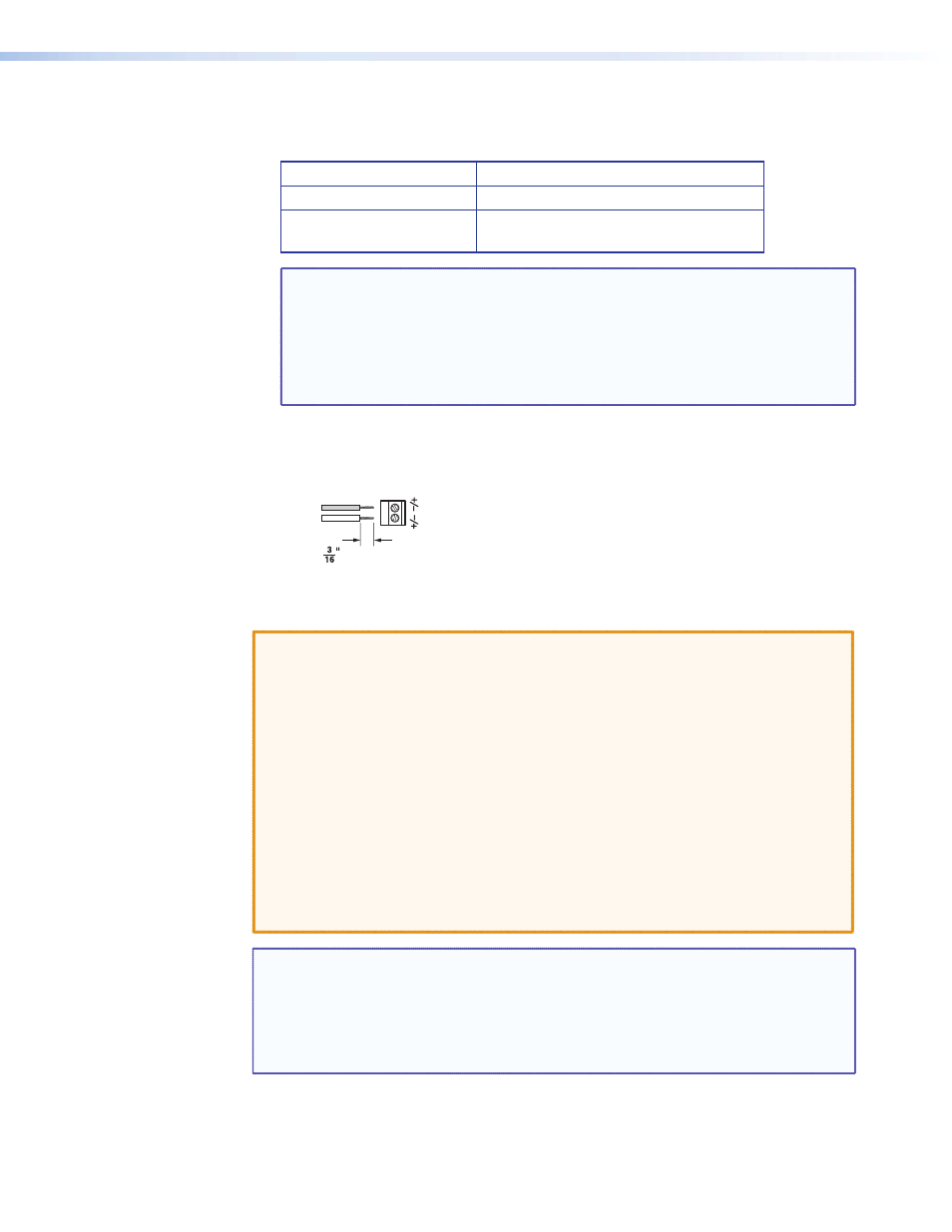
Power connector — Connect a 9 – 24 VDC power supply to this 3.5 mm, 2-pole, direct
insertion captive screw connector. Wire the connector as shown below. Polarity is not
important.
+ or –
– or +
9 – 24
VD
C
Po
wer
Do not tin the wires!
(5 mm) MAX.
Figure 6.
Power Connector Wiring
CAUTION: Always use a power supply supplied by or specified by Extron. Use of an
unauthorized power supply voids all regulatory compliance certification
and may cause damage to the supply and the end product. Extron power
supplies are certified to UL/CSA 60950-1 and are classified as LPS (Limited
Power Source). Use of a non-LPS or unlisted power supply will void all
regulatory compliance certification.
Unless otherwise stated, the AC/DC adapters are not suitable for use in
air handling spaces or in wall cavities. The power supply is to be located
within the same vicinity as the Extron A/V processing equipment in an
ordinary location, Pollution Degree 2, secured to the equipment rack
within the dedicated closet, podium or desk.
The installation must always be in accordance with the applicable
provisions of National Electrical Code ANSI/NFPA 70, article 75 and the
Canadian Electrical Code part 1, section 16. The power supply shall not be
permanently fixed to building structure or similar structure.
NOTES: The length of the exposed wires in the stripping process is critical. The ideal
length is 3/16 inches (5 mm). Any longer and the exposed wires may touch,
causing a short circuit between them. Any shorter and the wires can be easily
pulled out even if tightly fastened by the captive screws.
Do not tin the wires. Tinned wire does not hold its shape and can become
loose over time.