Reference material, Ethernet link, Choosing a network cable – Extron Electronics SMX System Setup Guide User Manual
Page 43: Terminating the network cable, Choosing a network cable terminating the network, Cable, Mounting the smx, Installing new boards, Crossover, Figure 29. rj-45 connector pinout tables
SMX System MultiMatrix Switcher • Reference Material
37
Reference Material
This section describes Ethernet links, connector wiring, mounting
methods, and board installation. Topics in this section includes:
•
•
•
Ethernet Link
The rear panel Ethernet connector on the SMX can be connected to an
Ethernet LAN or WAN. This connection allows for SIS control using a
computer connected to the same LAN. Ethernet cables must be of the
correct type, properly terminated relevant to the application, and with
the correct pinout.
Choosing a Network Cable
Use Category (CAT) 3, 4, 5, 5e, or 6 unshielded twisted pair (UTP) or
shielded twisted pair (STP) cables, terminated with RJ-45 connectors.
Ethernet cables are limited to 328 feet (100 m). Half-duplex and
full-duplex Ethernet connections are allowed. The cable used depends
on the network speed:
•
10 Mbps (10Base-T Ethernet) requires, at a minimum, CAT 3 UTP or
STP cable.
•
100 Mbps (100Base-T fast Ethernet) requires, at a minimum, CAT 5
UTP or STP cable.
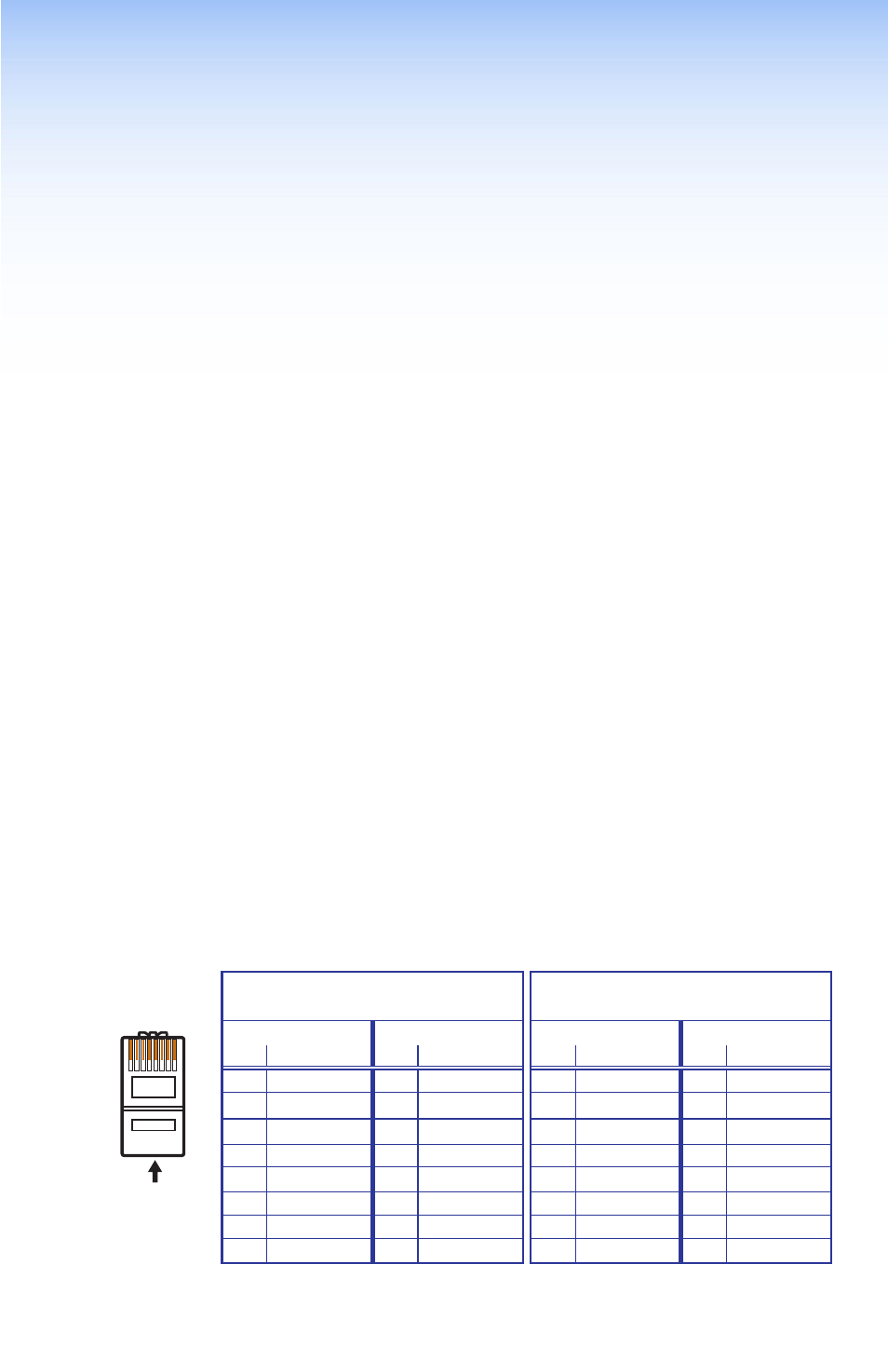
Terminating the Network Cable
Terminate as either a patch or a crossover cable (see
•
Crossover cable — Connection between the computer and the SMX.
•
Patch (Straight) Cable — Connection of the SMX to an Ethernet LAN.
Straight-through Cable
(for connection to a switch, hub, or router)
End 1
End 2
Pin Wire Color
Pin
Wire Color
1
white-orange
1
white-orange
2
orange
2
orange
3
white-green
3
white-green
4
blue
4
blue
5
white-blue
5
white-blue
6
green
6
green
7
white-brown
7
white-brown
8
brown
8
brown
Crossover
(for direct connection to a PC)
End 1
End 2
Pin Wire Color
Pin
Wire Color
1
white-orange
1
white-green
2
orange
2
green
3
white-green
3
white-orange
4
blue
4
blue
5
white-blue
5
white-blue
6
green
6
orange
7
white-brown
7
white-brown
8
brown
8
brown
Figure 29.
RJ-45 Connector Pinout Tables
12345678
RJ-45 Connector
Insert
Twisted
Pair Wires
Pins:
Side View
Straight-through Cable
(for connection to a switch, hub, or router)
End 1
End 2
Pin Wire Color
Pin
Wire Color
1
white-orange
1
white-orange
2
orange
2
orange
3
white-green
3
white-green
4
blue
4
blue
5
white-blue
5
white-blue
6
green
6
green
7
white-brown
7
white-brown
8
brown
8
brown
Crossover Cable
(for direct connection to a PC)
End 1
End 2
Pin Wire Color
Pin Wire Color
1
white-orange
1
white-green
2
orange
2
green
3
white-green
3
white-orange
4
blue
4
blue
5
white-blue
5
white-blue
6
green
6
orange
7
white-brown
7
white-brown
8
brown
8
brown