Cabling the switcher, Appendix b, cont’d, Pvs 305sa switcher • appendix b b-4 – Extron Electronics PVS 305SA User Guide User Manual
Page 54: Audio in l r video in, Audio in, Po wer, Switcher contr ol, Amplified output, Paging sensor (optional), A/v inputs
Appendix B, cont’d
PVS 305SA Switcher • Appendix B
B-4
L
R
L
R
L
R
A
UX A
UDIO
INPUT 5
LINE OUT
VOICELIFT RECEIVER
PA
GING
SENSOR
DO NO
T
GR
OUND
OR SHOR
T
SPEAKER OUTPUTS
1B RGB
1A RGB
2B RGB
2A RGB
3B RGB /VIDEO
4B RGB /VIDEO
3A RGB
4A RGB
I
N
P
U
T
S
RS-232 MLC/IR
2/4/
8
Ohms
CLASS 2
WIRING
AMPLIFIED A
UDIO OUT
V
OL/MUTE
Tx
Rx
IR
12V
10V
50mA
PO
WER
US
LI
ST
ED
17
TT
A
U
D
IO
/V
ID
EO
A
PP
A
R
AT
U
S
®
RGB
VIDEO
OUTPUTS
CONTR
OL
N15779
12V
5A MAX
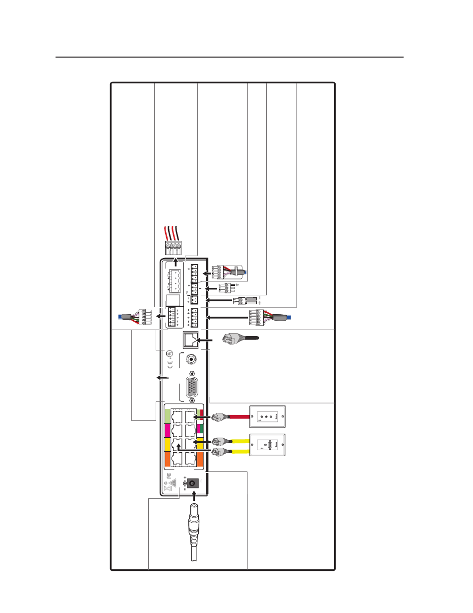
Connect this por
t to the MLS por
t on the MLC 104 IP Plus
.
The s
witcher po
wers the MLC 104 IP Plu
s.
Inser
t the round plug from
the supplied 12
VDC
, 5 A
po
wer supply
.
P
o
wer
Connect RGB and composite
video outputs to a displa
y de
vice
.
N
Optimal cab
le distance is betw
een 50 and 75 f
eet (15 and 22 m),
minimum distance is 15 f
eet (5 m).
CA
T 5/5e/6 rated.
Inputs 3 and 4 can be configured via RS-232 f
or either RGB
or composite video
(default)
.
C
Do NO
T connect this de
vice to a computer data or telecomm
unications netw
or
k.
Do NO
T shor
t output ter
minals to ground as it ma
y damage the s
witcher
.
Switcher Contr
ol
Pr
otocol:
9600 baud, 8 bit,1 stop bit, no par
ity
, no flo
w control
Connect one speak
er
(left and r
ight)
to each por
t
(red to positiv
e, b
lac
k to negativ
e).
If using more
than two spea
kers
, connect them in paralle
l
(i.e
., two to each po
rt).
Amplified Output
10V
Connect a Pr
ior
ity P
age Sensor (located near a pub
lic address system speak
er)
to this por
t (polar
ity unimpor
tant).
When sensing a P
A system broadcast, s
witcher
audio is muted.
P
aging Sensor (optional)
N
This po
wer supply is sufficient to
po
wer the s
witcher
, up to 4 A/V
w
allplates
, the
V
oiceLift receiv
er
,
and the MLC 104 IP Plus controller
.
4B VIDEO
Matching the cab
le colors to input por
ts
,
inser
t CA
T 5/5e/6 cab
les from w
allplates
.
A
UDIO IN
L
R
VIDEO IN
A/V Inputs
2A RGB
2B RGB
COMPUTER IN
A
UDIO IN
Connect an Extron e
xter
nal amplifier or an assistiv
e listening de
vice to
this por
t. Configure the por
t via RS-232 f
or fix
ed or
variable
(def
ault),
and wire f
or balanced or unbalanced audio
.
Connect an Extron e
xter
nal v
olume control modul
e, such as a
VCM, to this por
t.
DC
Volume Contr
ol (V
ol/Mute) (optional)
N1577
9
VOIC
US
LI
ST
ED
17
TT
A
U
D
A
PP
®
Connect this RJ-45
por
t to the OUT
por
t of an optional
V
oiceLift receiv
er
.
VoiceLift
®
Receiver
N
Ref
er to the
V
oiceLift System Manual
for more inf
or
mation
.
Input 5 is audio only
. No video signals on this input.
T
o s
witch to a line-le
vel audio signal
(balanced or unbalanced), connect the cab
le to this connector
.
A
ux A
udio Input 5
Line Out A
udio
1A RGB
2A RGB
3A RGB
4A RGB
2A RGB
1A RGB
4A RGB
3A RGB
1B RGB
2B RGB
3B RGB /VIDEO
4B RGB /VIDEO
1B RGB
2B RGB
RGB
VIDEO
3B
RGB VIDEO
4B
PVS 305SA Connections
Outputs
Cabling the Switcher