Preliminar y, Installation, cont’d, Dv d – Extron Electronics PVS 305SA User Guide User Manual
Page 19: Pvs 305sa rear panel, Host computer control system or, Ir link front and rear panels ir 452, Rs-232 port of a computer or control system
Installation, cont’d
PVS 305SA Switcher • Installation
2-10
PRELIMINAR
Y
PVS 305SA Rear Panel
L
R
L
R
L
R
AUX AUDIO
INPUT 5
LINE OUT
VOICELIFT
RECEIVER
PAGING
SENSOR
DO NOT
GROUND
OR SHORT
SPEAKER
OUTPUTS
1B RGB
1A RGB
2B RGB
2A RGB
RGB
VIDEO
RGB
VIDEO
3A RGB
4A RGB
I
N
P
U
T
S
RS-232 MLC/IR
2/4/8
Ohms
CLASS 2 WIRING
AMPLIFIED AUDIO OUT
VOL/MUTE
Tx Rx IR
12V
10V
50mA
POWER
US
LISTED
17TT
AUDIO/VIDEO
APPARATUS
®
RGB
VIDEO
OUTPUTS
CONTROL
N15779
12V
5A MAX
4B
3B
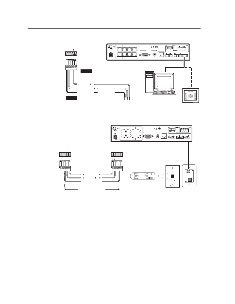
RS-232 port
of a computer or
control system
PVS 305SA
Switcher
rear panel
Control port
NOTE
If you use cable that has a
drain wire, tie the drain wire
to ground at both ends.
Tx Rx IR
+
12V
A B C D E
CONTROL
Host Computer
Control System
or
Transmit (Tx)
Receive (Rx)
3
2
Ground ( )
Transmit (Tx)
B Receive (Rx)
A
NOTE
Connect a ground wire
between the switcher and the
computer or control system.
Figure 2-11 — Connecting a computer or control system
CONTROL
Tx Rx IR
+
12V
PVS 305SA
Switcher
rear panel
Control port
IR Link
port
A B C D E
150 feet (45.7 m) maximum
+12 VDC
Ground ( )
IR
A B C D E
IR (IR Link)
C
D
IR Link front and rear panels
IR 452
SIGNAL
D
V
D
PVS 305SA Rear Panel
L
R
L
R
L
R
AUX AUDIO
INPUT 5
LINE OUT
VOICELIFT
RECEIVER
PAGING
SENSOR
DO NOT
GROUND
OR SHORT
SPEAKER
OUTPUTS
1B RGB
1A RGB
2B RGB
2A RGB
RGB
VIDEO
RGB
VIDEO
3A RGB
4A RGB
I
N
P
U
T
S
RS-232 MLC/IR
2/4/8
Ohms
CLASS 2 WIRING
AMPLIFIED AUDIO OUT
VOL/MUTE
Tx Rx IR
12V
10V
50mA
POWER
US
LISTED
17TT
AUDIO/VIDEO
APPARATUS
®
RGB
VIDEO
OUTPUTS
CONTROL
N15779
12V
5A MAX
4B
3B
Figure 2-12 — Connecting an IR Link to the switcher