Labeling the a/v inputs, Labeling and connecting the a/v input cables, Labeling and connecting the a/v input cables -12 – Extron Electronics PVS 305SA User Guide User Manual
Page 21: Preliminar y, Installation, cont’d
Installation, cont’d
PVS 305SA Switcher • Installation
2-12
PRELIMINAR
Y
Labeling the A/V Inputs
Labeling and connecting the A/V input cables
The RGB and composite video input ports on the rear of the PVS 305SA are color
coded to aid easy identification of the input signal type. A sheet of corresponding
colored labels is supplied for the installer to label the cables running from the PVT
Wallplates to the switcher. Once the labels are attached to the cables, the signal
type transmitted on any cable can clearly be identified, enabling correct cable
connection during installation.
To label the cables,
1
.
Peel off the label corresponding to the cable’s signal type (see the table below)
and affix it close to one end of the cable.
N
Align and press the colored section of the label to the cable first, then wrap the
clear section around the cable, allowing the signal type name to be easily read.
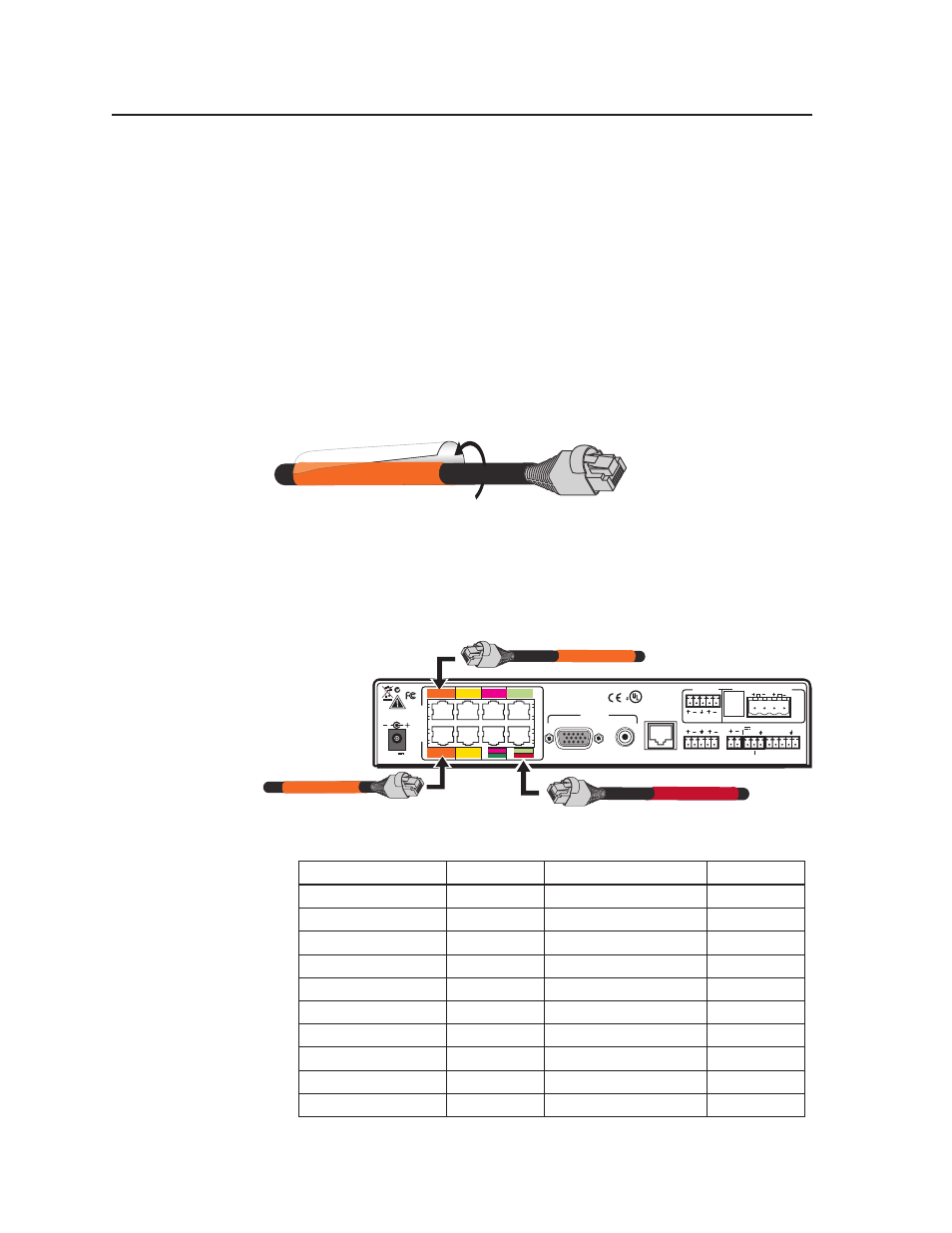
Figure 2-12 — Wrap the label around the cable, colored part first.
2
.
Repeat step 1 for the other end of the cable, using the same label type.
3
.
Using the correct label type, repeat steps 1 and 2 as necessary for all signal
cables that are to be connected to the PVS 305SA.
4
. Connect the colored coded cable to the corresponding color coded port (see
table below).
L
R
L
R
L
R
AUX AUDIO
INPUT 5
LINE OUT
VOICELIFT
RECEIVER
PAGING
SENSOR
DO NOT
GROUND
OR SHORT
SPEAKER
OUTPUTS
1B RGB
1A RGB
2B RGB
2A RGB
3B RGB
/VIDEO
4B RGB
/VIDEO
3A RGB
4A RGB
I
N
P
U
T
S
RS-232 MLC/IR
2/4/8
Ohms
CLASS 2 WIRING
AMPLIFIED AUDIO OUT
VOL/MUTE
Tx Rx IR
12V
10V
50mA
POWER
US
LISTED
17TT
AUDIO/VIDEO
APPARATUS
®
RGB
VIDEO
OUTPUTS
CONTROL
N15779
12V
5A MAX
1B RGB
2B RGB
RGB
VIDEO
3B
RGB
VIDEO
4B
RGB #1A
VIDEO #4
2A RGB
1A RGB
4A RGB
3A RGB
RGB #1B
Figure 2-13 — Connect the cables to the relevant input port.
Cable Input Signal Input Port # Background Color
Text color
RGB (cable A)
1A
Orange
Black
RGB (cable B)
1B
Orange
Black
RGB (cable A)
2A
Yellow
Black
RGB (cable B)
2B
Yellow
Black
RGB (cable A)
3A
Magenta
White
RGB (cable B)
3B
Magenta
White
RGB (cable A)
4A
Pale Green
Black
RGB (cable B)
4B
Pale Green
Black
Video
3B
Green
White
Video
4B
Red
White
RGB #1A