Wiring information, Signal cables, Line out audio cables – Extron Electronics PVS 305SA User Guide User Manual
Page 53: Switcher control cables, Signals, See appendix b, For wiring details, Aux audio input cables, Caution, Pvs 305sa switcher • appendix b
PVS 305SA Switcher • Appendix B
B-3
Wiring Information
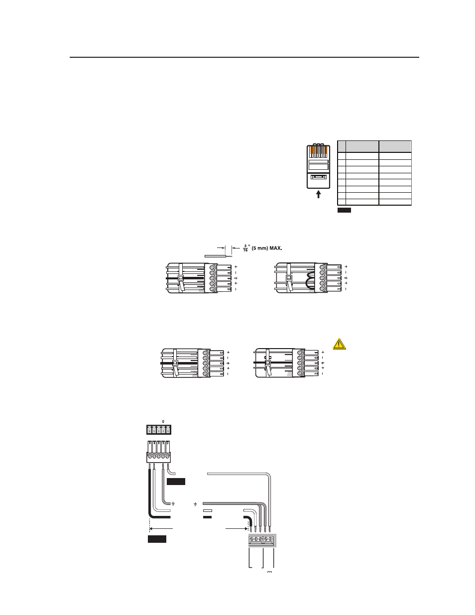
Signal cables
The PVS 305SA is capable of receiving signals from PVT wallplates located up to
100 feet (30 meters) away. The optimum distance is between 50 and 75 feet (15 and
22 meters)
. Minimum distance is 15 feet (4.6 meters).
The RGB cables supplied with the PoleVault
system are terminated to the TIA/EIA T568A
standard.
If other cables are used the RJ-45 termination
must comply with T568A or T568B wiring
standards, and the same standard MUST be
used at both ends of the cables.
Aux audio input cables
Wire the connector for the Aux audio input as balanced or unbalanced audio as
shown below.
Balanced audio
Tip
Ring
Tip
Ring
L
R
Sleeves
Do not tin the wires!
Unbalanced audio
Tip
Sleeve
Sleeve
Tip
L
R
Line out audio cables
Wire the connector for the Line Out output as balanced or unbalanced audio as
shown below.
Balanced audio
Tip
Ring
Tip
Ring
L
R
Sleeves
Unbalanced audio
Tip
Sleeve
Tip
L
R
CAUTION
For unbalanced audio, connect
the sleeve(s) to the ground contact.
DO NOT
connect the sleeve(s) to
the negative (-) contacts.
NO Ground here
NO Ground here
Switcher control cables
The connector for switcher control should be wired as shown below.
CONTROL
A B C
PVS 305SA Switcher's
rear panel
Control port
NOTE
A ground wire must be
connected between the MLC
and the switcher.
MLC 104 IP Plus
MLS and power ports
NOTE
If a cable that has a drain wire is
used, tie the drain wire to ground
at both ends.
D E
Tx Rx IR
+
12 V
RS-232 12V
MLS PWR
A B
Rx
Tx
GR
OUND
GR
OUND
+12V IN
Ground ( )
Transmit (Tx)
B Receive (Rx)
A
Transmit (Tx)
Receive (Rx)
B
A
+12 VDC input
50 feet (38 m) maximum
12345678
RJ-45
Connector
Insert Twisted
Pair Wires
Pins:
Pin
1
2
3
4
5
6
7
8
Wire color
White-green
Green
White-orange
Blue
White-blue
Orange
White-brown
Brown
Wire color
T568A
T568B
White-orange
Orange
White-green
Blue
White-blue
Green
White-brown
Brown
NOTE
If you are using Enhanced
Skew-Free™ A/V cable, use the
TIA/EIA T568A standard only.