Extron Electronics DXP Series User Manual
Page 48
5-7
Digital XPoint Matrix Switchers • Matrix Software
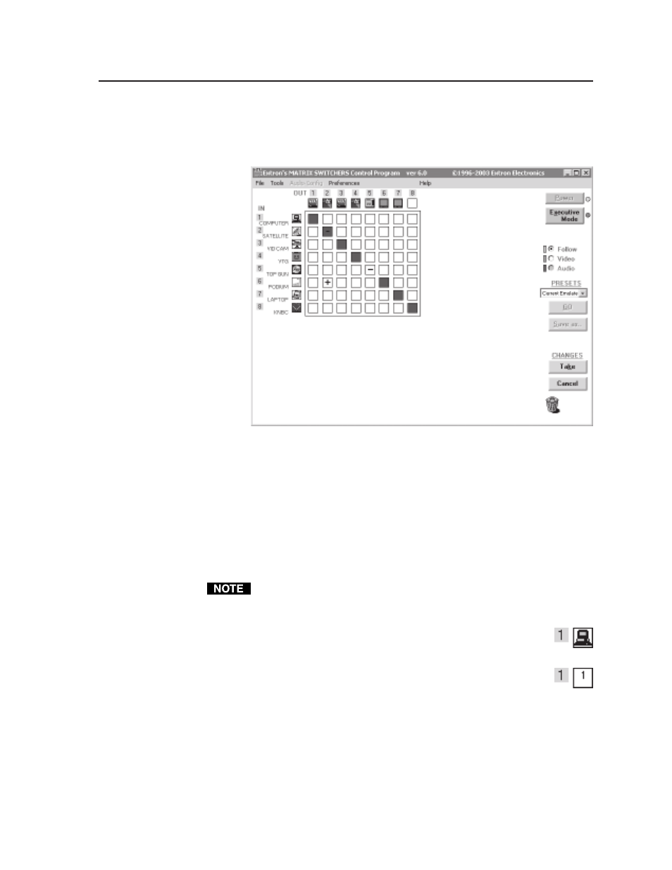
Ties as crosspoints —
Displays ties as a grid of inputs and outputs (figure 5-7).
Made ties are indicated as amber boxes. Ties that will take effect when
you click the Take button are indicated by +. Ties that will be broken
when you click the Take button are indicated by –.
Figure 5-7 — Ties shown as crosspoints
Frequency read options —
Allows you to set the input signal detection
feature as follows (see the inset box in figure 5-5):
•
To never sample and display the sync or no sync status
(set this option to None)
•
To automatically refresh the display
(set this option to Automatically every 10 seconds)
•
To sample the sync and update the display whenever you make
a configuration change
(set this option to On demand or by refresh).
The switcher always detects if an SDI signal is present. However, due to the
switcher’s input circuit sensitivity, the switcher may report that a signal is
detected when no signal is present at the input.
Icons in I/O boxes —
Erases any numbers in the I/O boxes in the
control program window (figure 5-4). You can place icons in
the boxes.
Numbers in I/O boxes —
Erases any icons in the I/O boxes in the
control program window and fills each box with the
associated input or output number.