Rs-232/422 connection, External sync connection, 5 digital xpoint matrix switchers • installation – Extron Electronics DXP Series User Manual
Page 16
2-5
Digital XPoint Matrix Switchers • Installation
RS-232/422 connection
4
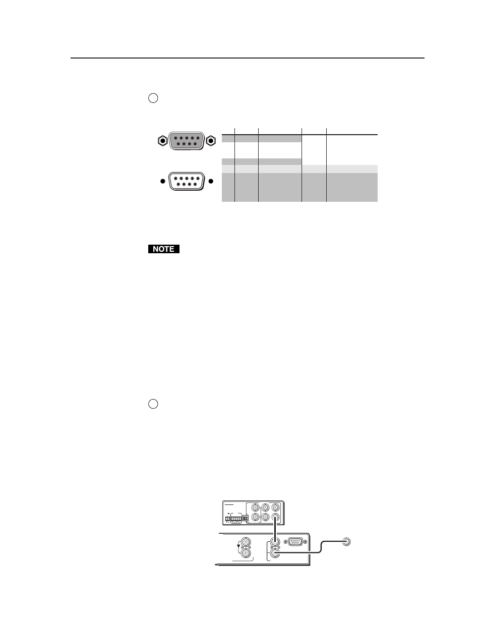
RS-232/RS-422 port
— If desired, connect a host device, such as a computer or
touch panel control, to the Digital XPoint via this 9-pin D connector for serial
RS-232/RS-422 control (figure 2-4).
Female
5
1
9
6
Male
1
5
6
9
RS-232 Function
Pin
1
2
3
4
5
6
7
8
9
—
TX
RX
—
Gnd
—
—
—
—
Not used
Transmit data
Receive data
Not used
Signal ground
Not used
Not used
Not used
Not used
RS-422 Function
TX-
TX+
RX+
RX-
Gnd
—
—
—
—
Transmit data (-)
Transmit data (+)
Receive data (+)
Receive data (-)
Signal ground
Not used
Not used
Not used
Not used
Figure 2-4 — RS-232/RS-422 port pin assignments
See chapter 4, “Programmer’s Guide”, for definitions of the SIS commands
and chapter 5, “Matrix Software”, to install and use the control software.
The Digital XPoint Series Matrix Switchers are factory configured for RS-232
control. To use the switcher under RS-422 control, an internal cable must be
moved. See chapter 6, “Maintenance and Modifications”, for the procedure for
swapping the serial ports.
If desired, connect an MCP 1000 remote control panel master unit to the
switcher’s RS-232/RS-422 connector. You can also connect an MKP 1000
remote keypad or MCP 1000 slave unit to the MCP 1000 master unit. Refer to
the MCP 1000 Remote Control Panel User’s Manual, part #68-456-01, and the
MKP 1000 User’s Manual, part #68-355-01, for details.
External sync connection
When switching between inputs, the resulting image change should be seamless, or
clean. The Digital XPoint Switchers can use an external signal to synchronize
switching during the vertical sync interval. Without the external sync locking
feature, switching between inputs can result in a brief rolling (sync loss) or a brief
change in the picture size.
5
External Reference In (top) connector —
Connect an external sync signal to
this BNC connection for genlocking the video signal in broadcast or other
sync-critical applications.
External Reference Out (bottom) connector
— Connect any downstream
equipment that requires genlocking to this BNC connector to route the
external sync signal throughout the system in broadcast or other sync-critical
applications.
Figure 2-5 shows a basic external sync configuration. The External Reference In
connector receives a timing signal. The External Reference Out connector allows
the signal to be passed on to another video device, if required.
Rear Panel
To Next Device
or Terminate
POWER
12V
.2A MAX
L
R
4
3
2
1
6
5
PA
L
NTSC
BLA
CKB
URST
BLACKBURST
COLORBARS
-10
+4
1 2 3
ON
1 KHZ
AUDIO
BBG 6 A
BLACKBURST AND AUDIO
GENERATOR
Extron
BBG 6 A
Blackburst/
Audio Generator
8
EXT. REF.
IN
RS232/422
OUT
IN
Figure 2-5 —Simple external sync connection example