Quick start — digital xpoint matrix switchers, Installation, Definitions – Extron Electronics DXP Series User Manual
Page 4: Front panel controls, Lcd displays, Step 1, Step 2, Step 3, Step 4, Step 5
QS-1
Digital XPoint Matrix Switchers • Quick Start
Quick Start — Digital XPoint Matrix Switchers
Installation
Step 1
Turn off power to the input and output devices,
and remove the power cords from them.
Step 2
Mount the switcher in a rack or under a table.
Step 3
Connect:
a
Up to 4 or 8 SDI inputs to the Input In (top)
connectors.
b
Up to 4 or 8 SDI displays or other devices to
the Input loop-through (bottom) connectors.
c
Up to 8 or 16 SDI display or other devices to
the Output connectors.
Each output number consists of two
identical SDI outputs.
Step 4
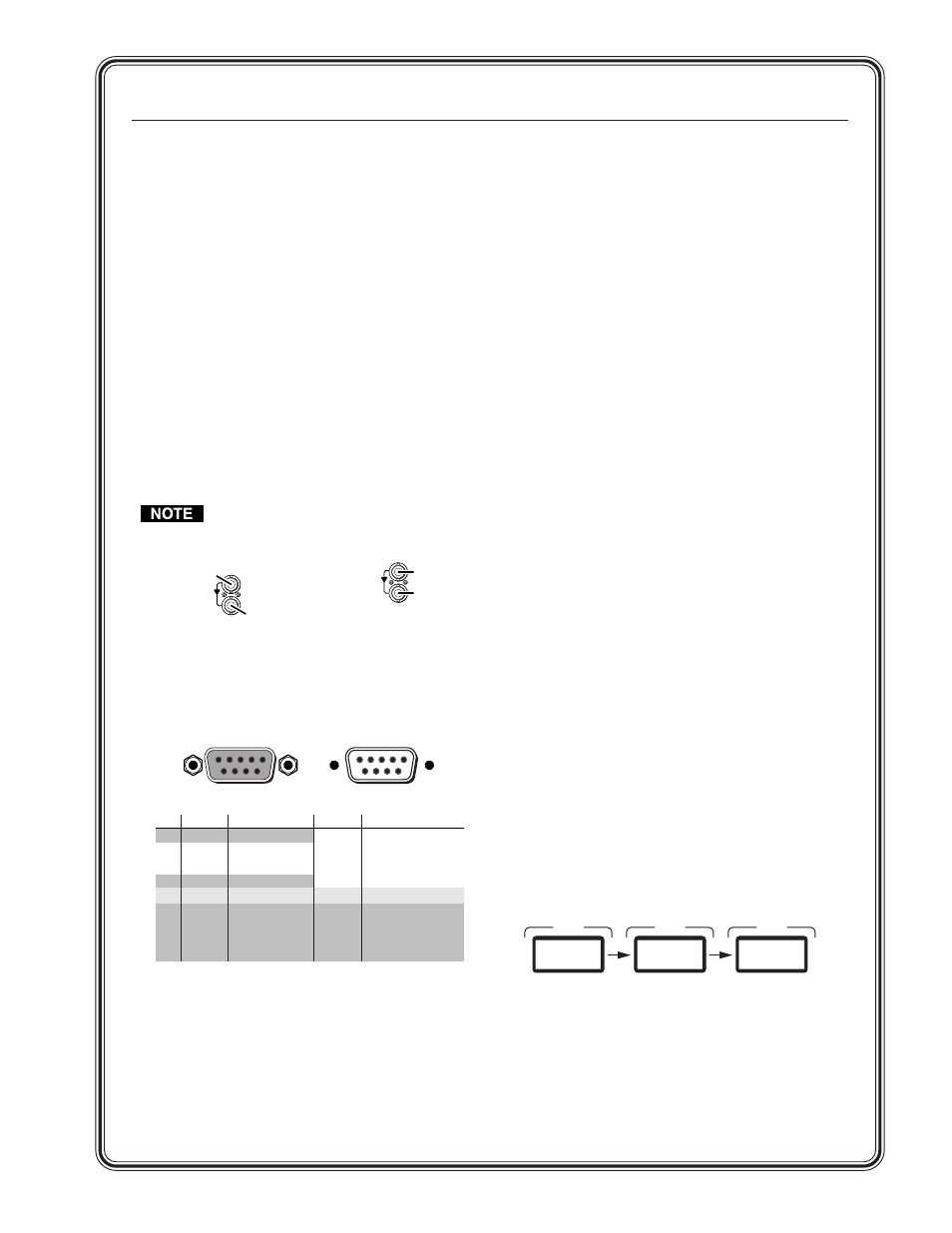
If desired, connect a control system or computer to
the RS-232/RS-422 port.
Step 5
If desired, attach an external sync timing device to
the external sync connectors.
Step 6
Plug the switcher, input devices, and output
devices into a grounded AC source, and turn on the
input and output devices.
Definitions
The following terms are used throughout this
manual:
Tie —
An input-to-output connection.
Set of ties —
An input tied to two or more outputs.
(An output can never be tied to multiple
inputs.)
Configuration —
One or more ties or sets of ties.
Current configuration —
The currently active
configuration
(also called configuration 0).
Preset —
A configuration that has been stored. One
preset
can be assigned to each input and output
button. Additional presets are available under
RS-232/422 control. When a preset is retrieved, it
becomes the current configuration.
Front Panel Controls
Input and output buttons
select and identify
inputs and outputs. The buttons also select
presets.
Enter button
saves changes when you change the
configuration.
Preset button
saves a configuration as a preset or
recalls a previously-defined preset.
Input and output buttons
can hold text or icon
inserts that can be created easily with Extron’s
label software.
LCD Displays
To view the current configuration, press and release
the button for the desired input. The LCD displays
the input number for approximately 1 second and
then the current configuration for approximately
10 seconds. The LCD displays each output number
on the top line and the tied inputs on the bottom
line. To check the status of another source, press
and release another Input button.
STATUS
1
Second
STATUS
STATUS
DXP 8 8
EXTRON
10
Seconds
I n p u t # 5
_
5
5
5
_
_
_ _
1 2 3 4 5 6 7 8
1
SDI
Source
SDI
Loop-through
3a
3b
1
SDI
Destination
SDI
Destination
3c
Female
5
1
9
6
Male
1
5
6
9
RS-232 Function
Pin
1
2
3
4
5
6
7
8
9
—
TX
RX
—
Gnd
—
—
—
—
Not used
Transmit data
Receive data
Not used
Signal ground
Not used
Not used
Not used
Not used
RS-422 Function
TX-
TX+
RX+
RX-
Gnd
—
—
—
—
Transmit data (-)
Transmit data (+)
Receive data (+)
Receive data (-)
Signal ground
Not used
Not used
Not used
Not used
4