Model mp, mpa, mpai, 8 dismantling – Xylem MPAI User Manual
Page 94
Installation, Operating and Maintenance Instruction
Model
MP, MPA, MPAI
MP 100-english
page 90
Revision 04
Article No 771074011
Issue 11/2011
rubber bellows with soap water shortly before it is
mounted. Do not use any mineral grease or oil if
you are not absolutely certain that the O-ring is
resistant to it.
Insert the countering of the mechanical seal
(GLRD) in the seal cap (18). Slide the rotating unit
of the mechanical seal (GLRD) onto the shaft
protective sleeve (44) and secure (if possible).
Work on mechanical seals with a rubber bellows
must now proceed quickly. This is the only way to
guarantee that the rotating mechanical seal
element can still be moved during assembly and
can be brought into the correct position.
Slide on the O-ring (OR4) and apply lubricating
agent (e.g. silicon grease) using a brush.
Lubricate the shaft protective sleeve (44) in the
borehole so that the O-ring groove remains clean
(start approx. 10-15mm inside). Standard O-rings
made of EP rubber are not resistant to mineral oil
or greases and must not come into contact with
them. Once resistance has been ascertained (e.g.
beef dripping as lubricant or oil-resistant O-rings)
the entire shaft may be lubricated.
Slide on the shaft protective sleeve (44). When
sliding on the shaft protective sleeve take care
that the O-ring can slide easily into the groove.
Insert the O-ring (OR3) in the casing and secure
with silicon grease. If possible, the O-ring should
lie touching the outer diameter (the O-ring can be
enlarged slightly by pulling).
Carefully mount the sealing cap (18), taking care
that the pin is in the correct direction (S4), (groove
in bearing flange).
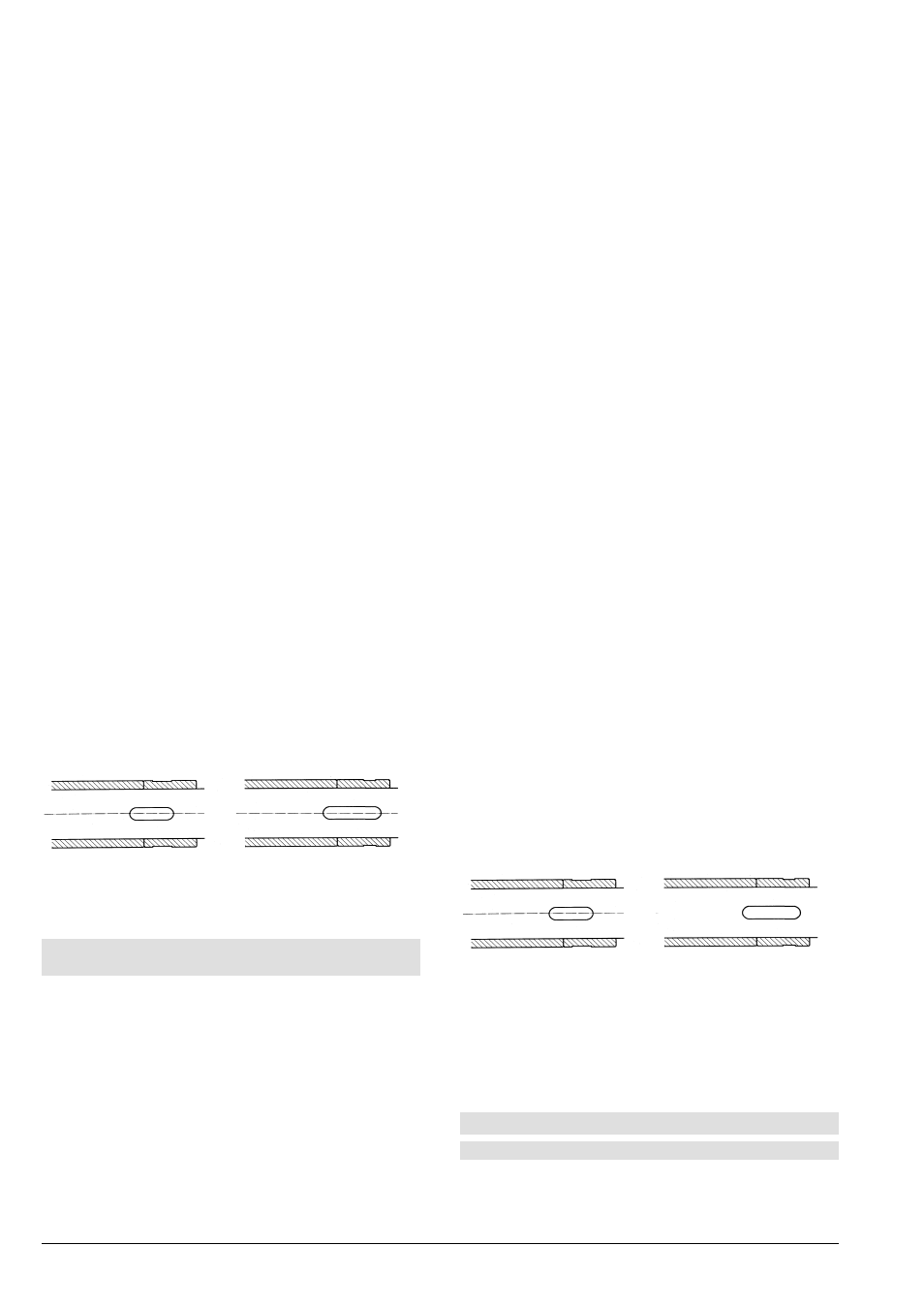
Insert feather key (PF3) and slide on the spacer
sleeve (72). Pump must be assembled in the
following direction.
MP, MPA 40, 65 and 100
MP, MPA 125
44 72
44 72
Slide on splash ring (73) and bearing cap (12)
For further assembly work see Point 3 (replacing
roller bearings) "Assembly".
8.7.3 Model with Cartridge Mechanical Seal (Code
"CS, CQ, CD")
See "Appendix" in the Operating Instructions for
sectional drawing
Description is valid for shaft seals on the intake (MP)
and discharge sides (MP,MPA, MPAI).
Normally the pump is fitted with two identical cartridge
mechanical seals.
In certain cases there may, however, be differences.
We recommend that parts are always marked before
dismantling.
The Appendix in the Operating Instructions contains a
detailed description of the cartridge mechanical seal.
Fix the rotating part of the cartridge mechanical
seal (GLRD) axially with the stationary part. For
this purpose, a fixing clamp (FB) (or similar
construction) is provided on the stationary part
(see sectional drawing).
Loosen nuts (M3) and screws (S9), cartridge
mechanical seal (GLRD) should move freely
Dismantle pump as described in Point 3 (replacing
roller bearings).
Remove bearing cap (12), spacer sleeve (72) and
splash ring (73).
Slide off cartridge seal (without shaft protective
sleeve) (44).
Take out feather key (PF3) and slide off shaft
protective sleeve (44). Remove O-ring (OR4).
Clean all parts and check for wear. Mechanical
seals must always be replaced. Repairing
mechanical seals is only recommended with
specialist training. Worn cartridge seal parts can
be replaced or repaired by the manufacturer.
Assembly
Always use a lubricant when mounting the
mechanical seal (e.g. silicon grease). Do not use
mineral grease or oil if you are not absolutely
certain that the O-ring is resistant to it.
Slide on the O-ring (OR4) and apply lubricant (e.g.
Silicon grease) with a brush.
Lubricate the shaft protective sleeve (44) in the
borehole so that the O-ring groove remains clean
(start approx. 10-15mm inside). Standard O-rings
made of EP rubber are not resistant to mineral oils
or greases and must not come into contact with
them. Once resistance has been ascertained (e.g.
beef dripping as lubricating agent or oil resistant
O-rings) the entire shaft may be lubricated (24)
Slide on the shaft protective sleeve (44). When
sliding on the shaft protective sleeve take care
that the O-ring can slide easily into the groove.
Slide on cartridge mechanical seal (GLRD) but do
not screw on tightly (M3 and S9 remain loose).
Insert feather key (PF3) and slide on the spacer
sleeve (72). Pump must be assembled in the
following direction.
MP, MPA 40, 65 and 100
MP, MPA 125
44 72
44 72
Slide on splash ring (73) and bearing cap (12)
For further assembly work see Point 3 (Replacing
Roller Bearings) "Assembly".
Finally tighten the nuts (M3) and then the screws
(S9) (must be done in this order). Bring fixing
clamp (FB) in its original position.
Rotate shaft (24) to see that it runs smoothly.
8.8 Dismantling
8.8.1 Model MPA, MPAI (axial intake pipe)
See "Appendix" in Operating Instructions for sectional
drawing