6 connecting an up/down water level instrument, External 12v battery – Xylem iRIS 150 GPRS DATALOGGERS User Manual
Page 41
35
–
IRIS 150 V1.11 User Guide
iQuest (NZ) Ltd - PO Box 15169, Hamilton, New Zealand Tel: +64 7 857-0810 Fax: +64 7 857-0811 Email: [email protected]
35
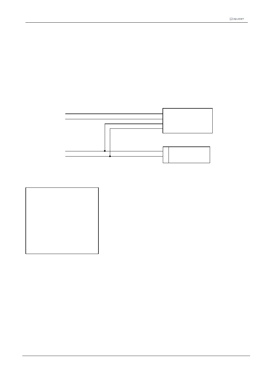
7.6 Connecting an Up/Down Water Level Instrument
A relatively common type of digital water level instrument is one that provides two pulse outputs. One output
generates a pulse for each increment and the other for each decrement in level. The iRIS maintains a
record of these steps and therefore the relative level.
These instruments normally require a 12V supply, which can also be used to provide external power to the
iRIS.
The diagram below shows the required connections for such an installation. The incrementing output must
be connected to DI1 and the decrementing output to DI2.
DI2
DI1
VIN+
GND (-)
A typical sensor configuration example for this type of installation is shown below. The instrument is a
standard digital up/down water level encoder. The level is averaged and the result logged every 15 minutes.
DN
Up/Down
UP
Water Level
+12V
Sensor
0V
External 12V
Battery
+
-
* Sensor 1 Cfg
(Now: 0.0)
0 Exit
1 Source [9: Up/Dn]
2 Name [Water Lvl]
3 Mode [Period Avg]
4 Multiplier [ 0.001]
5 Offset [ 0.000]
6 Log Multiplier [1000]
7 Log Rate [15min]
8 Alarms
9 Data