Xylem iRIS 150 GPRS DATALOGGERS User Manual
Page 20
iRIS 150 V1.11 User Guide - 14
14
iQuest (NZ) Ltd - PO Box 15169, Hamilton, New Zealand Tel: +64 7 857-0810 Fax: +64 7 857-0811 Email: [email protected]
5.3.3 Sensor Cfg (Level 3)
The Sensor Cfg menu is used to configure each of the four main virtual sensors. Refer to the datalogging
features (Section 2.5.2) of this manual for a discussion on virtual sensors. This menu also shows the current
scaled measurement value for this sensor
* Sensor 1 Cfg
(Now: 1.9620)
0 Exit
1 Source [1: Analog 1]
2 Name [Water Lvl]
3 Mode [Instant]
4 Multiplier [ 0.001]
5 Offset [ 0.0000]
6 Log Multiplier [1000]
7 Log Rate [15min]
8 Alarms
9 Data
>
Option 0
Select this option to return to the main Sensor Cfg menu.
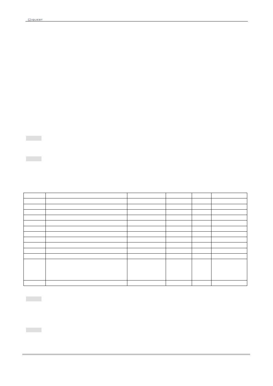
Option 1
When this option is selected you will be prompted to enter a number representing the source from which the
virtual sensor should acquire its data. Use zero to disable the sensor. A list of the valid data sources is
shown in the following table.
> Source (0..12)=
Source
Description
Raw Range
Multiplier
Offset
Log Multiplier
0
Unused / disabled
N/A
N/A
N/A
N/A
1
Analogue Input 1
0 to 5000
2
Analogue Input 2
0 to 5000
3
Pulse Counter on Digital Input 1
0 to 1
4
Pulse Counter on Digital Input 2
0 to 1
5
Auto Pulse Counter on Digital Input 1
0 to 1
6
Auto Pulse Counter on Digital Input 2
0 to 1
7
Frequency Counter on Digital In 1
0 to 5000Hz
8
Frequency Counter on Digital In 2
0 to 5000Hz
9
Up/Down Counter on Digital Ins 1 & 2
-32768 to 32767
10
Database Location
-32768 to 32767
11
DC Power Status
(Logs a single sample after a change
of state from off (0) to on (1) or vice-
versa.
0 to 1
1
0
1
12
SDI-12
Table 2- Sensor Sources
Option 2
When this option is selected you will be prompted to enter a name for the sensor (maximum 10 characters).
This name will be displayed on the applicable iRIS LCD sensor screens.
> Name (max 10)=
Option 3
When this option is selected you will be prompted to enter a number representing the processing mode.
> Mode (0..3)=