2 connecting a 0-5v pressure transducer, External 12v battery – Xylem iRIS 150 GPRS DATALOGGERS User Manual
Page 37
31
–
IRIS 150 V1.11 User Guide
iQuest (NZ) Ltd - PO Box 15169, Hamilton, New Zealand Tel: +64 7 857-0810 Fax: +64 7 857-0811 Email: [email protected]
31
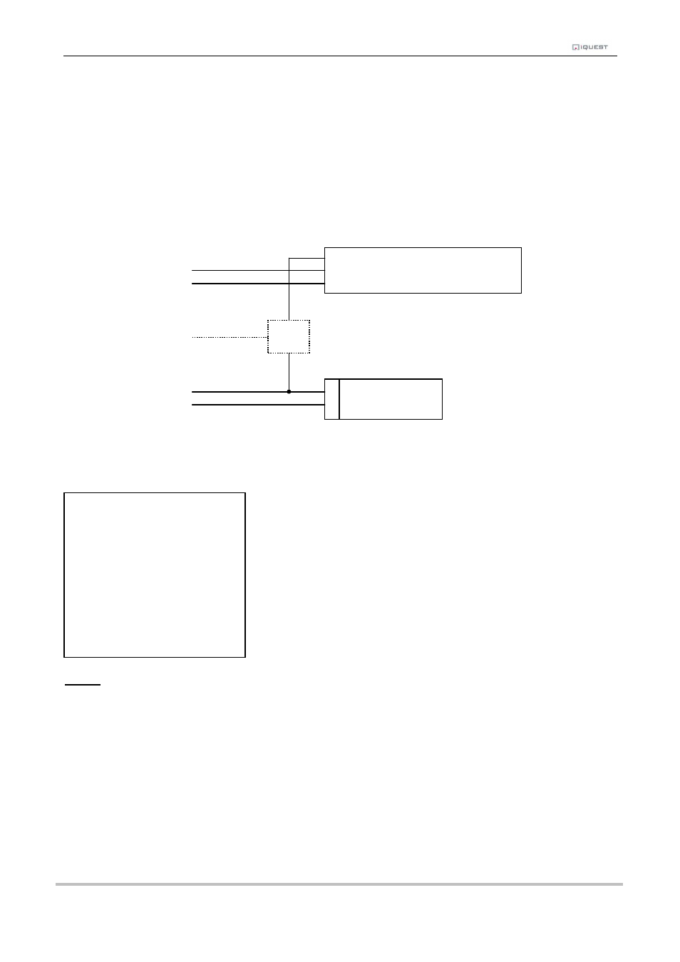
7.2 Connecting a 0-5V Pressure Transducer
Connecting a standard sensor (such as a pressure transducer that provides a 0-5V signal) to an iRIS is
relatively straightforward. An external 12V battery (7A/Hr or larger) is required to power the sensor but this
can optionally be controlled by the iRIS’ digital output to save power.
The diagram below shows the typical connection diagram for such an installation. It assumes the use of AI1
as the desired input channel. It also shows the connection of a transistor switch module with control from
DO1.
AI1
GND
DO1
+VIN
GND
The sensor should be configured for the correct channel, scaling and logging regime as described in Section
5.3.3. A typical sensor configuration example for this type of instrument is shown below. The instrument is a
10 metre, 0-5V output pressure transducer. The level is averaged and the result logged every 15 minutes.
NOTE: The iRIS supports activation of the digital output with a schedule. See Section for more
details and an example. Therefore, if further power reduction is to be achieved by controlling the
transducer power, follow this procedure:
1.
Install a transistor switch module in series with the transducer power lead and control it from
the digital output. See Appendix A for details on the transistor switch module.
2.
Configure the digital output’s mode to be Schedule (Mode = 0).
3.
Set up the digital output’s schedule to match the sensor’s logging period, but with the digital
output being set to activate the desired amount of time before the sensor is to log and with
sufficient “on” time to ensure an overlap with the logging time.
4.
Ensure the sensor mode is set to 0 (Instant).
Optional Transistor Switching Module
+
Signal Pressure Transducer
-
External 12V
Battery
+
-
* Sensor 1 Cfg
(Now: 0.0)
0 Exit
1 Source [1: Analog1]
2 Name [Water Lvl]
3 Mode [Period Average]
4 Multiplier [ 2.000]
5 Offset [ 0.0000]
6 Log Multiplier [1000]
7 Log Rate [15min]
8 Alarms
9 Data