4 measuring the external supply voltage – Xylem iRIS 150 GPRS DATALOGGERS User Manual
Page 39
33
–
IRIS 150 V1.11 User Guide
iQuest (NZ) Ltd - PO Box 15169, Hamilton, New Zealand Tel: +64 7 857-0810 Fax: +64 7 857-0811 Email: [email protected]
33
7.4 Measuring the External Supply Voltage
On occasions, it is useful to be able to measure the external supply voltage in real-time. This would typically
be in a telemetered installation where absolute battery health is important and an alarm can be raised on a
low level being detected at the base station.
Note: For maintaining a simple record of connection and disconnection of the external supply as a time-
stamped event based record, use sensor source 11 (DC Power). See Section 5.3.3 for more details.
To measure the external supply directly requires an analogue source to be configured. The voltage needs to
be measured by feeding the external supply voltage via a divider resistor into one of the analogue inputs.
The resistor should be 220K (220,000 ohms), 1% and one is supplied with every iRIS 150.
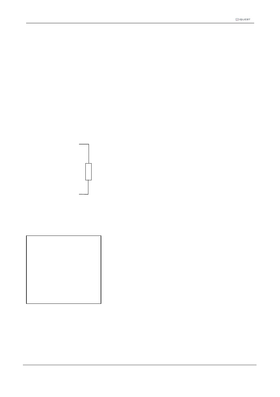
The diagram below shows the typical connection diagram for such an installation and shows the connection
of the potential divider resistor. It assumes the use of AI2 as the desired input channel. Because of the
small terminals in the iRIS, this resistor is more easily mounted externally and a separate wire (or cable core)
used to connect to the analogue input terminal.
AI2
VIN+
NOTE: The analogue input’s current selection jumper should be disconnected or the voltage
measured will be close to zero. No damage will occur however.
The sensor should be configured like the example shown below. In this example, analogue input 2 is used.
The voltage is averaged and the result logged every 60 minutes.
* Sensor 4 Cfg
(Now: 13.955)
0 Exit
1 Source [2: Analog2]
2 Name [Batt Volts]
3 Mode [Period Average]
4 Multiplier [ 0.0031]
5 Offset [ 0.0000]
6 Log Multiplier [100]
7 Log Rate [60min]
8 Alarms
9 Data
220K Resistor