External 12v battery – Xylem iRIS 150 GPRS DATALOGGERS User Manual
Page 38
iRIS 150 V1.11 User Guide - 32
32
iQuest (NZ) Ltd - PO Box 15169, Hamilton, New Zealand Tel: +64 7 857-0810 Fax: +64 7 857-0811 Email: [email protected]
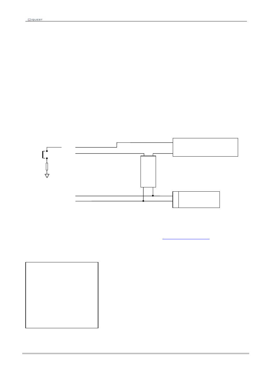
7.3 Connecting a 2-Wire Loop-Powered 4-20mA Sensor
The iRIS also supports the connection of many types of industry standard 4-20mA current loop instruments
such as ultrasonic or radar level sensors. A very common configuration used with these devices is known as
two-wire or loop-powered mode. This requires only two wires to the sensor and the 4-20mA loop current
provides power for the sensor as well as being the proportional analogue sensor signal.
These sensors often require a minimum voltage across them that may not be reliably achieved with a 12V
supply, taking into account the voltage drop across the sense resistor. In such cases, a separate 12-24V
boosted sensor supply is recommended.
The diagram below shows the recommended connection diagram for such an installation. It assumes the
use of AI1 as the desired input channel.
The iRIS has an internal 250
Ω
sense resistor that can be enabled by the use of jumpers J3 (AI1) and J4
(AI2), see section 4.2.3 for more information. The internal sense resistor generates a 1-5V signal (from the 4-
20mA current), which is then measured by the analogue input.
The sensor should be configured for the correct channel, scaling and logging regime as described in Section
5.3.3. An offset value will be required as part of the configuration, as the 4mA (1V) offset needs to be
eliminated. Use the iRIS Scaling Calculator to calculate the multiplier and offset. This supplied with the iRIS
support utility, “iTerm” which is available from the iQuest website at
http://www.iquest.co.nz
.
A typical sensor configuration example for this type of installation is shown below. The instrument is a 10
metre, 4-20mA output ultrasonic transducer. The level is averaged and the result logged every 15 minutes.
-
Signal 4-20mA Sensor
+
Isolated
12V – 24V
DC- DC
Converter
- +
24V
12V
- +
J3
Internal
250
Ω
Resistor
External 12V
Battery
+
-
AI1
GND
+VIN
GND (-)
* Sensor 1 Cfg
(Now: 0.0)
0 Exit
1 Source [1: Analog1]
2 Name [Water Lvl]
3 Mode [Period Average]
4 Multiplier [ 0.003]
5 Offset [ -2.5]
6 Log Multiplier [1000]
7 Log Rate [15min]
8 Alarms
9 Data