Xylem iRIS 150 GPRS DATALOGGERS User Manual
Page 21
15
–
IRIS 150 V1.11 User Guide
iQuest (NZ) Ltd - PO Box 15169, Hamilton, New Zealand Tel: +64 7 857-0810 Fax: +64 7 857-0811 Email: [email protected]
15
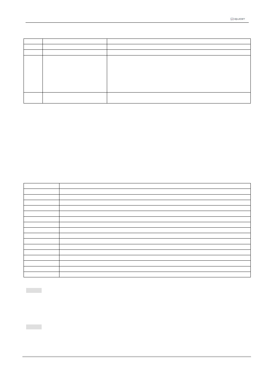
Valid modes are:
Mode
Name
Description
0
Instant
Logs only the most recent sample
1
Full Period Average
Logs the average of all samples taken over logging period
2
Event
(Only valid for pulse input sources) Logs non-zero samples.
If the logging rate is 0, then any pulse is logged immediately.
If the logging rate is > 0, then the total accumulated in the period is
logged only if it is not zero. In this mode, if there was no sample
logged at the last log time, a zero sample is also logged, time
stamped with last log time/date. This is required for time series
management purposes.
3
Scalar Average
(for Wind Direction)
Logs the average of all samples taken over logging period, but uses
scalar calculations to calculate the average.
Table 3- Sensors Modes
After selecting the mode, you will then be prompted to configure the extended datalogging options by
entering in a number that represents a set of option “flags”.
> Flags (+1:Min +2:Max +4:Dev +8:Flow or Total)=
The number entered is the sum of the extended logging options you want to enable. See the table
below for a listing of all the valid options.
Flag Value 1: Log Minimum Value sampled in log period
Flag Value 2: Log Maximum Value sampled in log period
Flag Value 4: Log Standard Deviation of samples in log period (not currently supported)
Flag Value 8: Log calculated Flow Rate over log period (only for sensors with pulse sources 3,4,5 or 6)
or
Log Accumulated Volume over log period (only for sensors with frequency sources 7or 8)
Flag Value
Description
0
No additional logging
1
Log Minimum
2
Log Maximum
3
Log Minimum and Maximum
4
Log Standard Deviation
5
Log Minimum and Standard Deviation
6
Log Maximum and Standard Deviation
7
Log Minimum, Maximum and Standard Deviation
8
Log Flow Rate or Total
9
Log Minimum and Flow Rate or Total
10
Log Maximum and Flow Rate or Total
11
Log Minimum, Maximum and Flow Rate or Total
12
Log Standard Deviation and Flow Rate or Total
13
Log Minimum, Standard Deviation and Flow Rate or Total
14
Log Maximum, Standard Deviation and Flow Rate or Total
15
Log Minimum, Maximum, Standard Deviation and Flow Rate or Total
Table 4- Sensor Logging Flags
Option 4
When this option is selected you will be prompted to enter a scaling multiplier. This multiplier is used to
convert the raw input into engineering units.
> Multiplier=
Option 5
When this option is selected you will be prompted to enter a scaling offset. This offset is added to the scaled
engineering value.
> Offset=