Zxbm1021, Functional descriptions – Diodes ZXBM1021 User Manual
Page 8
ZXBM1021
Document number: DS36322 Rev. 2 - 2
8 of 25
April 2014
© Diodes Incorporated
ZXBM1021
Functional Descriptions
(cont.)
C
LCK
– Locked Rotor Timing Capacitor
The C
LCK
pin will have a capacitor connected to ground. It is a multi-function pin providing timing for the lock detect, auto-restart and soft-start
conditions. Different rates of charge and discharge of C
LCK
capacitor depending on the mode of operation (fan operation status) give the soft-
start (T
SS
) to full speed, lock-detect time (T
LCKDET
) and lock time (T
OFF
) before next auto-start retry. When the motor is running, the capacitor is
discharged at every Hall signal change.
C
LCK
pin provides the timing for the Locked Rotor monitor. In normal operation, and after the soft-start period, Lock Detect is enabled. If the Hall
signal does not change (i.e. a rotor lock condition) within the Lock Detect time (T
LCKDET
), the outputs are disabled. In this condition the motor will
not be driven for a set time T
OFF.
This T
OFF
time depends on the external C
LCK
capacitor value and its internal discharge current (I
LCKDL
). After
the T
OFF
period device goes into a soft-start period (T
SS
) to re-start the motor. If the motor has not turned to generate a transition on the Hall
inputs by the end of this period, motor re-enters motor lock T
OFF
period with outputs disabled. Once the fan is running normally at the end of a
soft-start period, the motor is deemed as running and goes into lock-detection mode.
The time periods of T
SS
, T
LCKDET
and T
OFF
are determined by the value of the external capacitor on the C
LCK
pin and the internal charge and
discharge currents during these time periods. The currents during T
SS
, T
LCKDET
and T
OFF
are I
LCKCL
, I
LCKCR
and I
LCKDL
respectively.
During soft-start mode, the SetThRef voltage is increased from 0 to Vref. A potential divider from SetThRef is used to generate SetTh voltage for
current limit. As SetThRef ramps to nominal value, current limit set also ramps from 0 to nominal setting. This gradual release of current limit to
full speed level provides the soft-start.
FG
–
Frequency Generator (Tachometer) Output
This is the Frequency Generator output and is a buffered signal from the Hall sensor. This is an open collector drive giving an active pull down
with the high level being provided by an external pull up resistor.
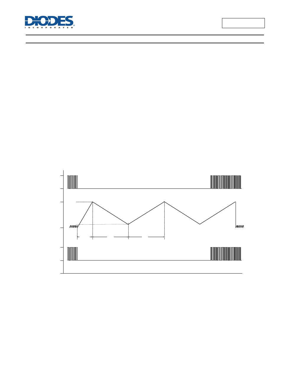
T
LCKDET
T
OFF
T
ss
Hall
C
LCK
FG
V
THH
V
THL
FG Timing Diagram