Functional block diagram, Zxbm1021 – Diodes ZXBM1021 User Manual
Page 4
ZXBM1021
Document number: DS36322 Rev. 2 - 2
4 of 25
April 2014
© Diodes Incorporated
ZXBM1021
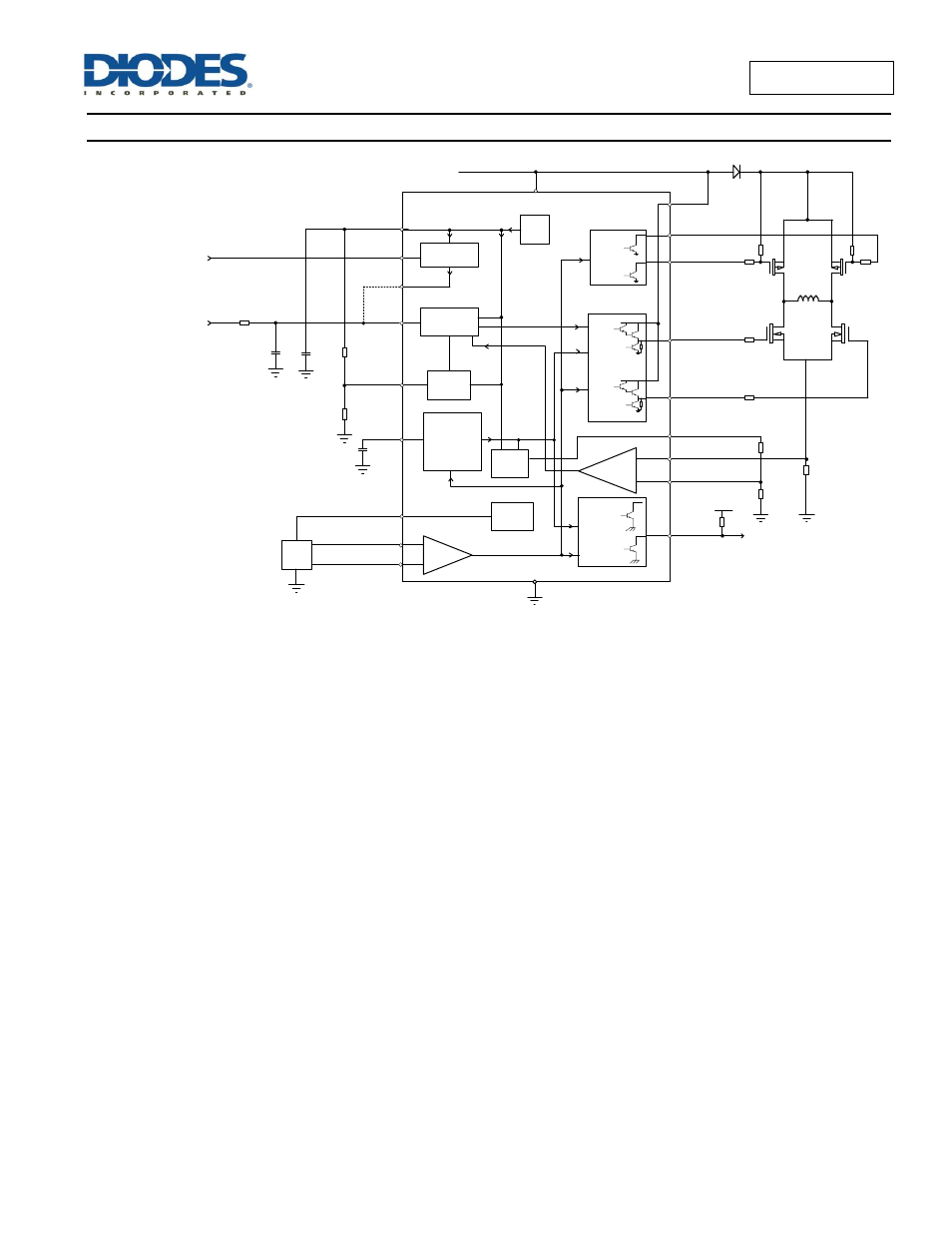
Functional Block Diagram
(Note 5)
Speed &
Lock
Detect
Hall
FG
C
LCK
SPD
H+
H-
Hall
Amp
PWM
Integrator
Locked
Rotor
Detect
Phase
Drive &
Control
Gnd
Vcc
Set Min
Speed
Vref
SMIN
ThRef
Ph2 Lo
Ph1 Lo
Ph2 Hi
Ph1 Hi
Vcc
Vcc
Phase
Drive
Current
Monitor
SetTh
Sense
Voltage Speed Control
V
SPD
Vcc
Vcc
Hall
Bias
HBIAS
Start-up
SetThRef
PWM
SPD
PWM speed control
PWMSPD
C
SPD
D2
RD
V+OP
PWM Osc
Note:
5. The ZXBM1021 has an open-collector FG. Typically a pull-
up resistor of 10kΩ is recommended from FG pin to the supply voltage.
See also other documents in the category Diodes Hardware:
- PDS3200 (5 pages)
- PDS340 (5 pages)
- PDS340Q (5 pages)
- PDS360 (5 pages)
- PDS360Q (5 pages)
- PDS4150 (4 pages)
- PDS3100Q (5 pages)
- PDS3100 (5 pages)
- PDS1240CTL (5 pages)
- PDS1045 (5 pages)
- PDS1040L (5 pages)
- PDS1040CTL (5 pages)
- PDS1040 (5 pages)
- PD3S230L (5 pages)
- PD3S230H (3 pages)
- PDS5100Q (5 pages)
- PDS835L (5 pages)
- PDS760 (5 pages)
- PDS560 (5 pages)
- PDS540 (5 pages)
- PDS5100H (5 pages)
- PDS5100 (5 pages)
- PDS4200H (6 pages)
- SBL3060CTP (4 pages)
- SBL30L30CT (3 pages)
- SBL3045CTP (4 pages)
- SBL3040CTP (4 pages)
- SBL2060CTP (4 pages)
- SBL2030CT - SBL2060CT (3 pages)
- SBL2045CTP (4 pages)
- SBL1060CTP (4 pages)
- SBL1040CTP (4 pages)
- SBG3030CT - SBG3045CT (5 pages)
- SB520 - SB560 (3 pages)
- SB370 - SB3100 (3 pages)
- SB320 - SB360 (3 pages)
- SBR10U100CT (5 pages)
- SBR10U150CT (5 pages)
- SBR10A45SP5 (5 pages)
- SBR1060CT (5 pages)
- SBR1045SP5 (5 pages)
- SBR1045SD1 (4 pages)
- SBR1045D1 (5 pages)
- SBR1045CTL (4 pages)
- SBR1040CT (5 pages)