Zxbm1021, Application information – Diodes ZXBM1021 User Manual
Page 15
ZXBM1021
Document number: DS36322 Rev. 2 - 2
15 of 25
April 2014
© Diodes Incorporated
ZXBM1021
Application Information
(cont.)
Example: Required I
LIM
= 2A
IM
where SetThRef = (ThRef -0.1V) = 4.9V typical
Ω
Solve for R7
7
.9
8
Choose R8 = 2k
and solve for R7 which gives R7 = 47k
.
The current in R7+R8 string = 4.9/49000 = 100µA which is within maximum output current capability of the SetThRef pin.
It is important that the current limit be set above the intended average current of the motor. In practice, due to the variable nature of the motor
current through a commutation cycle, it is usually necessary for the current limit to be set higher than the peak current drawn at the beginning of
each commutation cycle.
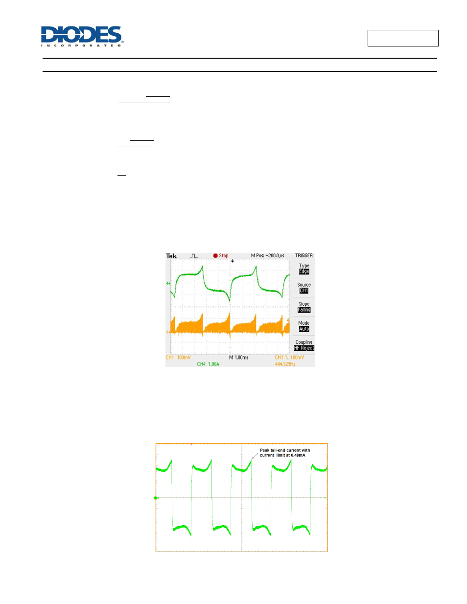
The top trace shows the motor coil current, while the lower trace shows the Sense pin voltage. As the current flow direction in the motor coil
changes at each commutation cycle, the motor current in the top trace is shown as positive and negative current. The current flowing in the
Rsense is always in the same direction and therefore the sense pin reads the magnitude of the motor coil current.
Current limiting may prevent the motor from reaching full speed, despite the average current being significantly lower than the current limit. The
system will limit the tail-end current according to the current limit set. Current limit setting can also be used to remove the tail-end current.
Example of using current limit to reduce tail-end current at full speed is shown in fibelow
Current limit set much higher than the peak tail-end current
(Peak tail-end current = 180mA typ, Current limit set at 0.485mA )