Application information, Zxbm1021 – Diodes ZXBM1021 User Manual
Page 11
ZXBM1021
Document number: DS36322 Rev. 2 - 2
11 of 25
April 2014
© Diodes Incorporated
ZXBM1021
Application Information
The ZXBM1021 is primarily controlled by a voltage on the SPD pin or a PWM signal on the PWMSPD pin.
A voltage of 1V represents a 100% PWM at the Phase Outputs and in turn represents full speed. 3V on the SPD pin conversely represents 0%
PWM. The motor can therefore be controlled simply by applying a control voltage onto the SPD pin with the minimal use of external components.
This voltage control method easily lends itself to control by other signal types. For example if a thermistor is applied to the SPD pin a varying
voltage can be generated at the SPD pin as the resistance of the thermistor varies with temperature.
A common form of control of fans is by a PWM signal derived from a central processor or controller. This speed control PWM signal can be
applied to PWMSPD pin. Motor speed is proportional to the duty ratio of the applied PWM speed control signal on PWMSPD pin.
Voltage on the S
MIN
pin sets the minimum speed of the motor. If the speed demand by either DC signal on SPD pin or PWM signal on PWMSPD
pin is lower than the minimum speed setting, motor will run at minimum speed.
The design of a motor system will be set around the maximum speed, the minimum speed and the current of the motor. The design of the motor
coil and the voltage on the output stage will set the maximum speed of the motor.
The ZXBM1021 allows easy setting and control of the minimum speed and maximum motor current, as well as for controlling the speed.
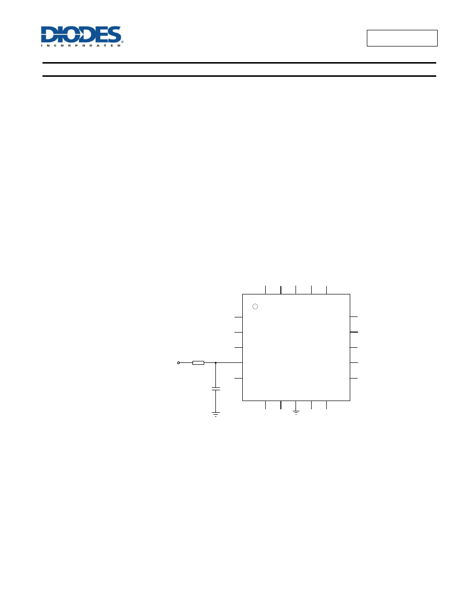
DC Speed Control
The SPD pin will respond to an input DC voltage from 3V to 1V for 0% to 100% of the full speed. To allow internal minimum speed setting (SMIN)
and current control (ILIM) circuits to adjust the SPD pin voltage, the speed control DC voltage signal should be driven in via a 10k
Ω series
resistor. The series resistor allows the SPD pin to vary even when driven externally by a low impedance source. A 0.1µF capacitor should be
connected from the SPD pin to supply ground.
When used in DC speed control mode, PWMSPD and C
SPD
pins should be left floating.
V
C
C
H
+
ThRef
PWMSPD
C
SPD
C
L
C
K
P
h
2
H
i
H
-
SPD
S
M
IN
F
G
Ph1Lo
Ph2Lo
Ph1Hi
SetThRef
Sense
S
e
tT
h
G
N
D
HBIAS
ZXBM1021
1
2
3
4
5
6
7
8
9
10
15
14
13
12
11
20
19
18
17
16
V
+
O
P
0.1µF
DC Speed Control
(3V to 1V)
R
10k
Ω
C