Typical applications circuit, Zxbm1021 – Diodes ZXBM1021 User Manual
Page 2
ZXBM1021
Document number: DS36322 Rev. 2 - 2
2 of 25
April 2014
© Diodes Incorporated
ZXBM1021
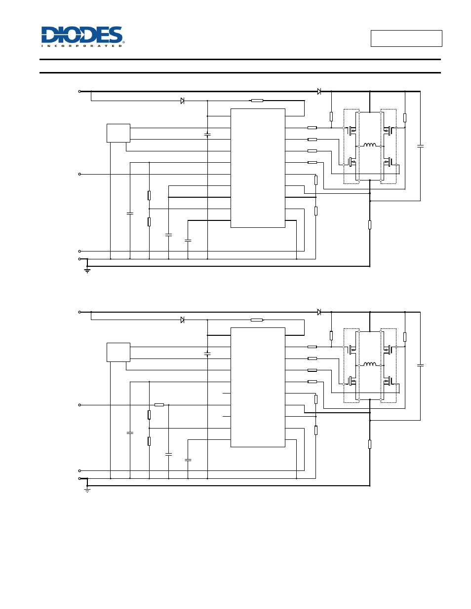
Typical Applications Circuit
(Note 4)
ZXBM1021
V
CC
H+
H-
C
LCK
SPD
C3
C2
C1
1µF
0.1uF
0.47µF
0V
FG
Typical Applications Circuit for PWM Control
using the ZXBM1021 and ZXMC MOSFET 1/2 Bridge Drivers
ThRef
S
MIN
Ph1Lo
Ph2Lo
GND
Q1-4
W1
470
Ω
R2
470
Ω
ZXMC
3A17DN8
FG
Ph1Hi
Ph2Hi
R1
R5
R3
R4
R6
100
Ω
100
Ω
1k
Ω
1k
Ω
C5
2.2µF
12V
D1
1N4148
D2
1N4004
SetTh
Sense
PWM control
R10
16k
Ω
R9
12k
Ω
Hall
R8
470
Ω
R7
33k
Ω
Rsense
0.1
Ω
3
3
4
4
5 & 6
5 & 6
7 & 8
7 & 8
2
2
1
1
SetThRef
PWMSPD
C
SPD
0.1µF
C4
V+OP
HBIAS
R12
(Optional)
ZXBM1021
V
CC
H+
H-
C
LCK
SPD
C3
C2
C1
1µF
0.1uF
0.47µF
0V
FG
Typical Applications Circuit for DC Control
using the ZXBM1021 and ZXMC MOSFET 1/2 Bridge Drivers
ThRef
S
MIN
Ph1Lo
Ph2Lo
Gnd
Q1-4
W1
470
Ω
R2
470
Ω
ZXMC
3A17DN8
FG
Ph1Hi
Ph2Hi
R1
R5
R3
R4
R6
100
Ω
100
Ω
1k
Ω
1k
Ω
C5
2.2µF
12V
D1
1N4148
D2
1N4004
SetTh
Sense
R10
16k
Ω
R9
12k
Ω
Hall
R8
470
Ω
R7
33k
Ω
Rsense
0.1
Ω
3
3
4
4
5 & 6
5 & 6
7 & 8
7 & 8
2
2
1
1
SetThRef
PWMSPD
C
SPD
0.1µF
C4
V+OP
HBIAS
DC control
R11
10k
Ω
R12
(Optional)
Note:
4. FG pull-up resistor is not shown in the typical application circuit. Generally, the FG pull-up resistor is located at the system host end rather than the
fan motor PCB.