Application information, Zxbm1021, Pwm speed control – Diodes ZXBM1021 User Manual
Page 12
ZXBM1021
Document number: DS36322 Rev. 2 - 2
12 of 25
April 2014
© Diodes Incorporated
ZXBM1021
Application Information
(cont.)
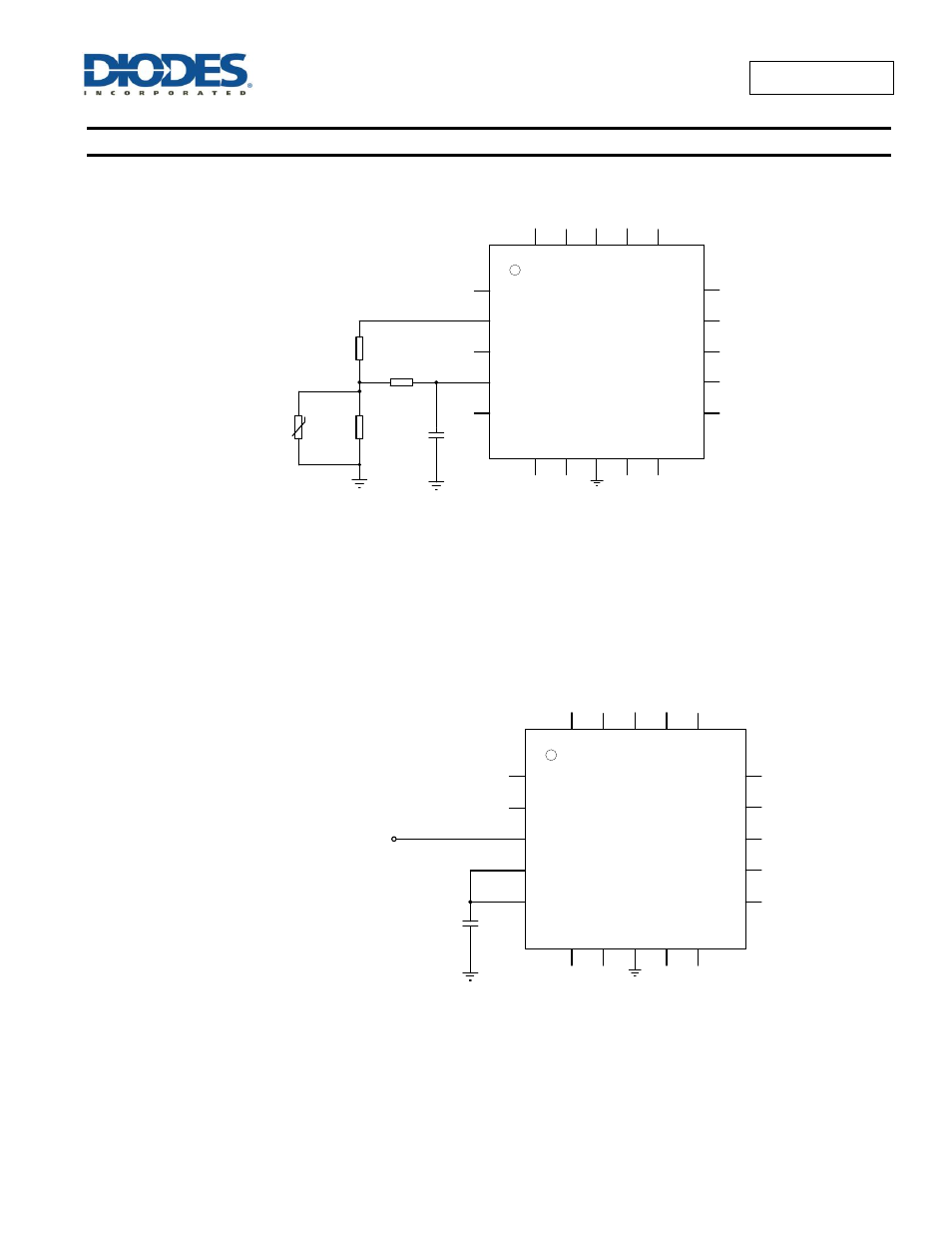
This input also allows the fan to be driven by a thermistor, to allow the speed to be controlled according to temperature. An example circuit is
shown below.
With the values shown, and a Beta value of 4000 for the NTC, the above circuit drives the ZXBM1021 with 3V (minimum speed) at 0
o
C, changing
to 1V (maximum speed) at 82
o
C, subject to tolerances. To minimize additional circuitry, the 5V ThRef output from the ZXBM1021 IC can supply
the current required for the thermistor network circuit as long as the total current from ThRef does not exceed 10mA.
PWM Speed Control
An additional input allows for the use of PWM to
control the fan speed. The ZXBM1021’s output speed is proportional to the duty cycle of the
PWM input.
When using PWMSPD speed input, the SPD pin should be connected to C
SPD
with a 0.1
F capacitor connected to ground. PWMSPD can be
driven from a microcontroller with either 0-5V or 0-3.3V logic levels signal. The recommended frequency of the input PWM control signal is
25kHz.
H
+
ThRef
PWMSPD
P
h
2
H
i
H
-
SPD
F
G
Ph1Lo
Ph2Lo
Ph1Hi
SetThRef
Sense
S
e
tT
h
G
N
D
HBIAS
ZXBM1021
1
2
3
4
5
6
7
8
9
10
15
14
13
12
11
20
19
18
17
16
V
+
O
P
0.1µF
R11
10k
Ω
C4
R12
4.7k
Ω
R13
9.1k
Ω
NTC
10k
Ω
C
L
C
K
S
M
IN
C
SPD
V
C
C
V
C
C
H
+
ThRef
PWMSPD
C
SPD
C
L
C
K
P
h
2
H
i
H
-
SPD
S
M
IN
F
G
Ph1Lo
Ph2Lo
Ph1Hi
SetThRef
Sense
S
e
tT
h
G
N
D
HBIAS
ZXBM1021
1
2
3
4
5
6
7
8
9
10
15
14
13
12
11
20
19
18
17
16
V
+
O
P
0.1µF
PWM Speed Control
(TTL level, Duty ratio 0% to 100%)
C4