Asus AP2400R-E2(AS8) User Manual
Page 77
A S U S A P 2 4 0 0 R - E 2
A S U S A P 2 4 0 0 R - E 2
A S U S A P 2 4 0 0 R - E 2
A S U S A P 2 4 0 0 R - E 2
A S U S A P 2 4 0 0 R - E 2
4 - 1 5
4 - 1 5
4 - 1 5
4 - 1 5
4 - 1 5
1 1 .
1 1 .
1 1 .
1 1 .
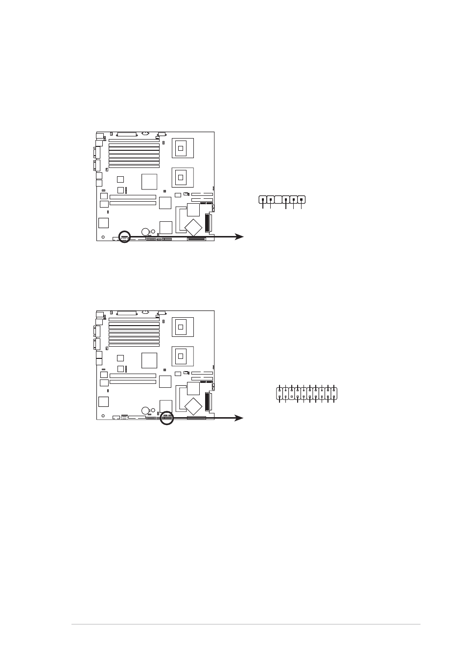
1 1 . Backplane SMBus connector (6-1 pin BPSMB1)
B a c k p l a n e S M B u s c o n n e c t o r ( 6 - 1 p i n B P S M B 1 )
B a c k p l a n e S M B u s c o n n e c t o r ( 6 - 1 p i n B P S M B 1 )
B a c k p l a n e S M B u s c o n n e c t o r ( 6 - 1 p i n B P S M B 1 )
B a c k p l a n e S M B u s c o n n e c t o r ( 6 - 1 p i n B P S M B 1 )
This connector allows you to connect SMBus (System Management
Bus) devices. Devices communicate with an SMBus host and/or other
SMBus devices using the SMBus interface.
®
NCL-DS1R2
NCL-DS1R2 SMBus connector
BPSMB1
1
I2C_6_CLK#
GND
I2C_6_DA
T
A
#
+5V
F
AN_DC
1 2 .
1 2 .
1 2 .
1 2 .
1 2 . System panel connector (20-pin PANEL1)
S y s t e m p a n e l c o n n e c t o r ( 2 0 - p i n P A N E L 1 )
S y s t e m p a n e l c o n n e c t o r ( 2 0 - p i n P A N E L 1 )
S y s t e m p a n e l c o n n e c t o r ( 2 0 - p i n P A N E L 1 )
S y s t e m p a n e l c o n n e c t o r ( 2 0 - p i n P A N E L 1 )
This connector supports several chassis-mounted functions.
®
NCL-DS1R2
NCL-DS1R2 System panel connector
PANEL1
MLED-
GND
NC
POWERBTN#
+5V
GND
GND
NC
POWERLED+
HDLED+
NC
HDLED-
POWERLED-
MLED+
NMIBTN#
GND
RESETBTN#
SPKROUT
GND
•
S y s t e m p o w e r L E D ( G r e e n 3 - p i n P L E D )
S y s t e m p o w e r L E D ( G r e e n 3 - p i n P L E D )
S y s t e m p o w e r L E D ( G r e e n 3 - p i n P L E D )
S y s t e m p o w e r L E D ( G r e e n 3 - p i n P L E D )
S y s t e m p o w e r L E D ( G r e e n 3 - p i n P L E D )
This 3-pin connector is for the system power LED. Connect the
chassis power LED cable to this connector. The system power
LED lights up when you turn on the system power, and blinks
when the system is in sleep mode.
•
H a r d d i s k d r i v e a c t i v i t y L E D ( R e d 2 - p i n I D E _ L E D )
H a r d d i s k d r i v e a c t i v i t y L E D ( R e d 2 - p i n I D E _ L E D )
H a r d d i s k d r i v e a c t i v i t y L E D ( R e d 2 - p i n I D E _ L E D )
H a r d d i s k d r i v e a c t i v i t y L E D ( R e d 2 - p i n I D E _ L E D )
H a r d d i s k d r i v e a c t i v i t y L E D ( R e d 2 - p i n I D E _ L E D )
This 2-pin connector is for the HDD Activity LED. Connect the
HDD Activity LED cable to this connector. The IDE LED lights up
or flashes when data is read from or written to the HDD.
•
S y s t e m w a r n i n g s p e a k e r ( O r a n g e 4 - p i n S P E A K E R )
S y s t e m w a r n i n g s p e a k e r ( O r a n g e 4 - p i n S P E A K E R )
S y s t e m w a r n i n g s p e a k e r ( O r a n g e 4 - p i n S P E A K E R )
S y s t e m w a r n i n g s p e a k e r ( O r a n g e 4 - p i n S P E A K E R )
S y s t e m w a r n i n g s p e a k e r ( O r a n g e 4 - p i n S P E A K E R )
This 4-pin connector is for the chassis-mounted system warning
speaker. The speaker allows you to hear system beeps and
warnings.