Asus AP2400R-E2(AS8) User Manual
Page 75
A S U S A P 2 4 0 0 R - E 2
A S U S A P 2 4 0 0 R - E 2
A S U S A P 2 4 0 0 R - E 2
A S U S A P 2 4 0 0 R - E 2
A S U S A P 2 4 0 0 R - E 2
4 - 1 3
4 - 1 3
4 - 1 3
4 - 1 3
4 - 1 3
7 .
7 .
7 .
7 .
7 .
U S B c o n n e c t o r ( 1 0 - 1 p i n U S B 3 4 )
U S B c o n n e c t o r ( 1 0 - 1 p i n U S B 3 4 )
U S B c o n n e c t o r ( 1 0 - 1 p i n U S B 3 4 )
U S B c o n n e c t o r ( 1 0 - 1 p i n U S B 3 4 )
U S B c o n n e c t o r ( 1 0 - 1 p i n U S B 3 4 )
This connector is for USB 2.0 ports. Connect the USB module cable to
this connector, then install the module to a slot opening at the back
of the system chassis. This USB connector complies with USB 2.0
specification that supports up to 480 Mbps connection speed.
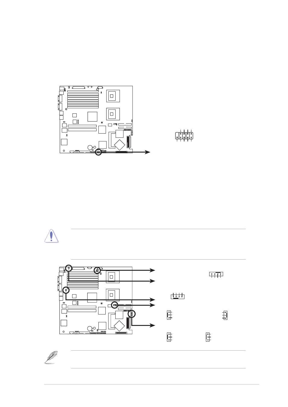
8 .
8 .
8 .
8 .
8 .
C P U a n d s y s t e m f a n c o n n e c t o r s ( 4 - p i n C P U _ F A N 1 / 2 ,
C P U a n d s y s t e m f a n c o n n e c t o r s ( 4 - p i n C P U _ F A N 1 / 2 ,
C P U a n d s y s t e m f a n c o n n e c t o r s ( 4 - p i n C P U _ F A N 1 / 2 ,
C P U a n d s y s t e m f a n c o n n e c t o r s ( 4 - p i n C P U _ F A N 1 / 2 ,
C P U a n d s y s t e m f a n c o n n e c t o r s ( 4 - p i n C P U _ F A N 1 / 2 ,
3 - p i n R E A R _ F A N 1 / 2 , F R N T _ F A N 1 / 2 )
3 - p i n R E A R _ F A N 1 / 2 , F R N T _ F A N 1 / 2 )
3 - p i n R E A R _ F A N 1 / 2 , F R N T _ F A N 1 / 2 )
3 - p i n R E A R _ F A N 1 / 2 , F R N T _ F A N 1 / 2 )
3 - p i n R E A R _ F A N 1 / 2 , F R N T _ F A N 1 / 2 )
The fan connectors support cooling fans of 350 mA ~ 740 mA (8.88 W
max.) or a total of 2.1 A ~ 4.44 A (53.28 W max.) at +12V. Connect
the fan cables to the fan connectors on the motherboard, making sure
that the black wire of each cable matches the ground pin of the
connector.
Do not forget to connect the fan cables to the fan connectors.
Insufficient air flow inside the system may damage the motherboard
components. These are not jumpers! Do not place jumper caps on the
fan connectors!
®
NCL-DS1R2
NCL-DS1R2 USB connector
USB34
Power
1
USB PortA(-)
USB PortA(+)
GND
Power
USB PortB(-)
USB PortB(+)
GND
NC
®
NCL-DS1R2
CPU_FAN1
FRNT_FAN2
CPU_FAN2
FRNT_FAN1
GND
F
AN Power
F
AN Speed
PWM Control
GND
F
AN Power
F
AN Speed
PWM Control
NCL-DS1R2 Fan connectors
GND
Rotation
+12V
GND
Rotation
+12V
REAR_FAN1
GND
Rotation
+12V
GND
Rotation
+12V
REAR_FAN2
CPU_FAN1
REAR_FAN2
REAR_FAN1
FRNT_FAN2
FRNT_FAN1
CPU_FAN2
The CPU_FAN1 connector is attached to the mid-fan board. All system
fans will rotate in full speed when you disconnect the CPU_FAN1 cable.