Recommended measurement device chart, Measurement points and meters, Item measurement precision measurement – GE Industrial Solutions AF-300C AC Drive User Manual
Page 91
GEK-85718
input Side
Output Side
(Power Side)
(Electric Motor Side)
Symbol of
Instrument
Input Side Measuring
(Power Side)
Amperemeter
AR, S, T
Movable Core
Voltmeter
VR,
T
Rectifier Type
or Movable Core
Wattmeter
W R , T
mometer Type
Item
Measurement of Output Freq.
Terminals FM1 and FM2
Name of
Instrument
Kind of
lnetrument
DC Voltmeter
V
Movable Coil Type
Symbol of
Instrument
Output Side Measuring lnst
(Electric Motor Side)
Wattmeter
w u , w
dynamo-
meter Tvoe
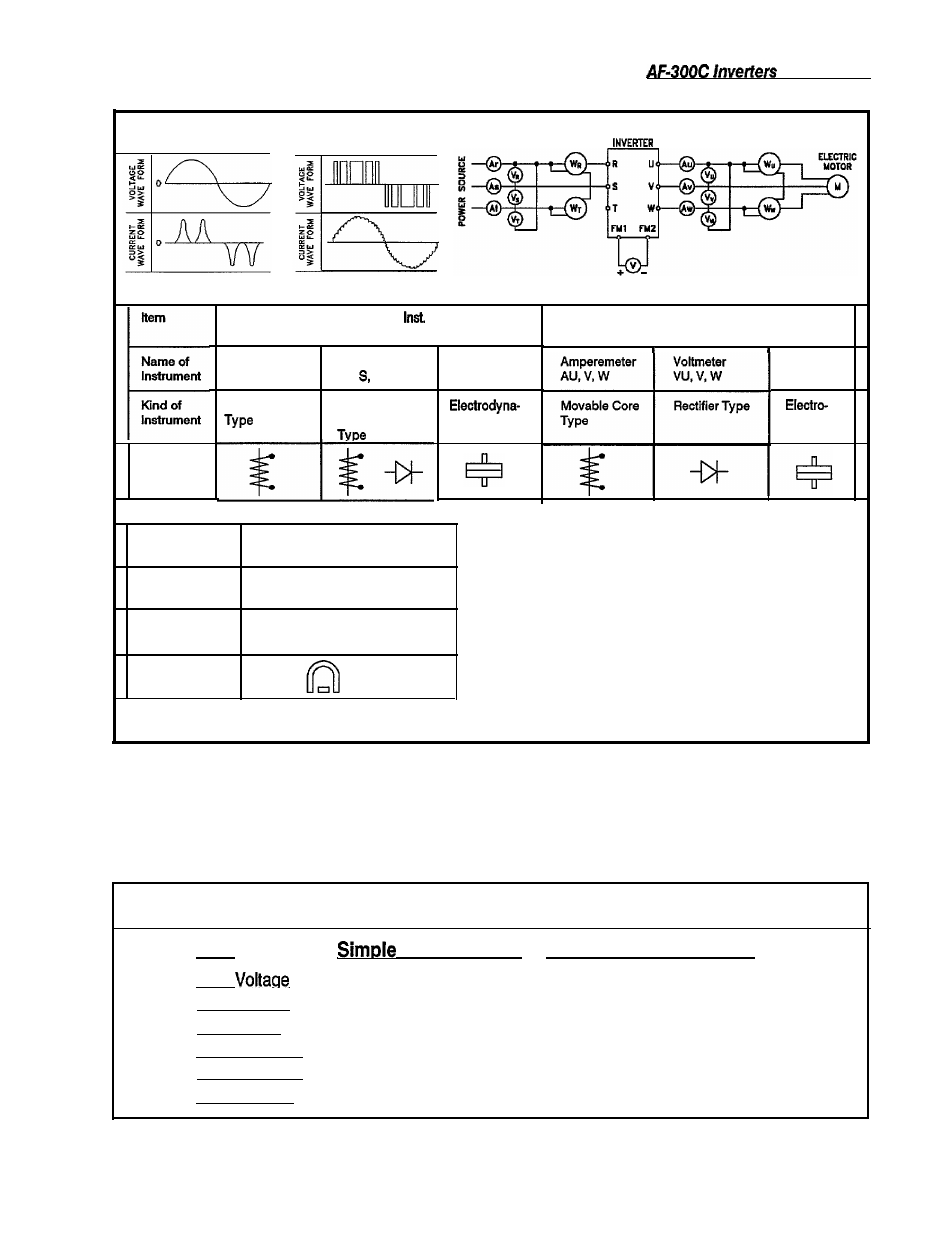
Figure 7-2. MEASUREMENT LOCATIONS AND DEVICES EXAMPLE
MEASUREMENT POINTS AND METERS
Since the inverter input/output voltage and current
contains high frequencies, selection of the wrong
measuring device can lead to gross miscalculations.
When using a CT (current-detection transformer) to
measure the current, the amount of error will be large
if the frequency is low. Because of this, always use a
CT with as large a capacity as possible. See the fol-
lowing chart and Figure 7-2 for recommended meas-
urement devices.
RECOMMENDED MEASUREMENT DEVICE CHART
Item
Measurement Precision Measurement
Input
Tester
Moving-Iron type voltmeter
Input Current
Clamp Meter
Moving-Iron type ammeter
Input Power --
Electrodynamometer type wattmeter
Output Voltane
Tester
Rectifier type voltmeter
Output Current
Clamp Meter
Moving-Iron type ammeter
Output Power --
Electrodynamometer type wattmeter
7-3