Continued), Table 2: terminal – GE Industrial Solutions AF-300C AC Drive User Manual
Page 44
GEK-85718
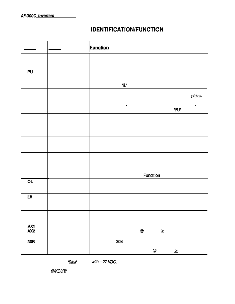
TABLE 2: TERMINAL
(continued)
Terminal
Terminal
Label
Name
CONTACT
INPUT:
(continued)
IL
OPEN COL-
LECTOR
OUTPUT*:
CME
RUN
FAR
FDT
Undervoltage Stop
CONTACT
OUTPUT:
30A
3oc
Commercial To lnverter When PU-CM is closed, reference increases and preparation for
inverter operation is made. When set to OFF after a fixed time,
inverter will operate. (Used for open transfer Line-lnverter-Line; also
used with terminal
for transfer.)
Output Starter
When providing an output starter, its auxiliary contact (normally
Interlock
closed) must be between IL-CM (closed). When the starter
up, the auxiliary contact must open (IL-CM open) permitting inverter
operation. IL-CM On interrupts inverter operation; IL-CM Off
continues inverter operation. Used with terminal
for transfer.
Open Collector Comm. Common terminal for output of open collectors.
lnverter In Operation
Transistor turns ON between RUN-CME at start frequency and
above. Transistor turns OFF when inverter is stopped, during coast
stop, and DC braking.
Set Frequency
When the set frequency is reached (inverter is up-to-speed),
Detection Signal
FAR-CME will be ON. See Function Code 36.
Optional Detection of
FDT-CME will be on when the output frequency is larger than the set
Frequency Level
detection frequency; FDT-CME will be OFF when output frequency
is less than set frequency. See
Code 35.
lnverter Overload Early OL-CME will be on when the output current is larger than the set
Warning Signal
value; OL-CME will be OFF when output current is less than set
current. See Function Code 32.
LV-CME will be on when an undervoltage condition exists. LV-CME
will be off when the DC link voltage is above the trip threshold. N o
output will occur for a set time after power-up.
Run Relay Dry Contact Contact is closed when the inverter is running. (Contact rating:
output
250 VAC, 0.3 Amps inductive cos theta 0.3)
Fault Relay Dry
Contact Output
During normal operation, the relay is not energized and contact is
made between
and 30C. When a fault is detected, the relay is
energized and contact is made between 30A and 30C. (Contact
rating: 250 VAC, 0.3 Amps inductive
cos theta 0.3)
*Open collector outputs are
circuits
50mA maximum ratings. Power for these circuits
must be provided via an external power supply when using them to control external relays (see Figure 4-13.)
The Relay Option
has this power supply built in.
4-12