GE Industrial Solutions AF-300C AC Drive User Manual
Page 25
GEK-85718
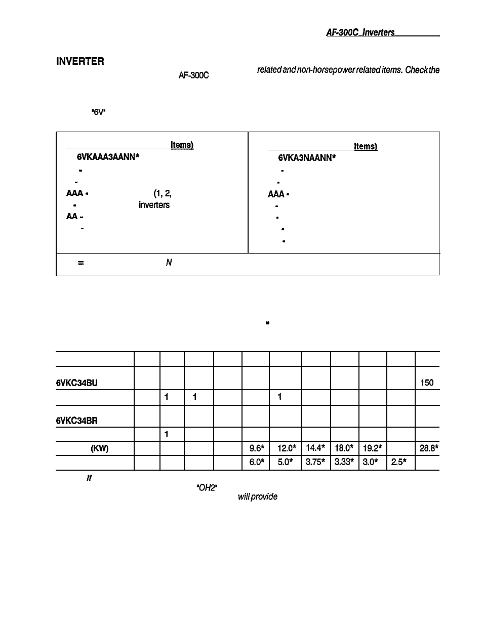
OPTIONS
Various options are available for the
Inverter.
These options can be ordered from the supplier of the
inverter per the GE Catalog Number shown on the
chart within this paragraph. The General Electric
Company
catalog numbers are coded as shown
in the following Examples:
NOTE: Option charts are divided into horsepower
horsepower of the inverter before ordering options to
be sure the correct option is ordered.
Example: (Non-HP Related
6V GE Drives Products Operation
K Option Kit
Applicable Series
or 3 characters)
3 AF-300 Family of
Option Abreviation
NN Option Size/Length (if applicable)
Example: (HP Related
6V GE Drives Products Operation
K Option Kit
Applicable Series
3 AF-300 Family of inverters
N Voltage
AA Option Abreviation
NN Horsepower Rating (2 or 3 characters)
*A alphabetical character, = Numerical char.
AF-300C HORSEPOWER RELATED OPTIONS Braking Units and Braking Resistors
(See Section
4
for recommended wiring.)
Horsepower
40
50
60
75
100
125
150
175
200
250
300
Braklng Unit
050
050
075
075
150
150
150
175
150
150
- - -
Quantity Req.
1
1
1
1
1
2
2
2
Braklng Resistor
040
050
060
075
050
060
075
060
050
060
075
- - -
Quantity Req.
1
1
1
2
2
2
3
4
4
4
Capacity
3.6
4.8
6.0
7.2
24.0”
Resistance (Ohms)
15
12
10
7.5
1.88”
NOTE:
the braking unit or resistor overheats, the thermal switch opens which turns off the braking unit
transistors and trips the inverter on an
fault (provided thermal interlocks are wired correctly).
These
recommended braking unit and resistor combinations
up to 100% braking torque with a maximum 5%
duty cycle (maximum continuous ON time of braking unit is 60 seconds).
*Total value, not for one resistor.
2-9