GE Industrial Solutions AF-300C AC Drive User Manual
Page 18
GEK-85716
4. Avoid storage in humid environments or in
atmospheres that contain corrosive gases such
as sulferized gas, ammonia gas, or chlorine
gas.
NOTE:
is stored or
a
where construction work is still being done, keep
prorecred from exposure
water and dust
is be placed in service.
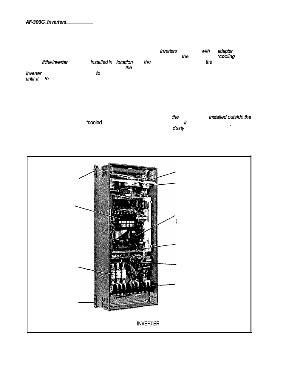
INVERTER COMPONENTS AND COOLING
Refer to Figure 2-2 for identification and location of
inverter components. There are two types of cooling
methods depending on the installation method, “cooled
inside control enclosure’ and
outside control
enclosure’ (see Figure 2-3).
lnverters rated 200,250, and 300 HP can be mounted
“Cooled Inside Control Enclosure”. However, a
mounting pedastal will need to be constructed that
can support the weight of the inverter.
This pedastal should mount to the bottom of the
inverter.
NOTE:
are shipped
the
mounted
for ‘cooling inside
enclosure’. If
outside
enclosure” is required,
adapter must be
repositioned (see Figure 2-3).
The mounting adapter, positioned at either the top or
bottom of the enclosure, must be located in accordance
with the installation/cooling method.
With the “cooled outside the enclosure” method, the
cooling fan is mounted externally and approximately
60% of the total heat generated by the inverter is
discharged outside the unit.
NOTE:
When
cooling fan is
control enclosure, must be periodically cleaned
(especially in
environments).
Mounting
Adaptor
Keypad
Panel
AC Line .
Fuses (3)
Mounting
Adaptor
Control Cooling Fan
Charge
Contactor
Main Control Card
(Base Driver is integral
on this Card)
Control Circuit
Terminal Board
Ground Fault
Detection Card
Main Circuit
Terminal Board
Figure 2-2.
TYPICAL
COMPONENTS
2-2