GE Industrial Solutions SG Series 10 – 20 – 30 – 40 kVA Operating Manual User Manual
Page 21
Modifications reserved
Page 21/83
OPM_SGS_USM_10K_40K_0US_V030.doc
Operating Manual SG Series 10 –20 – 30 - 40 kVA
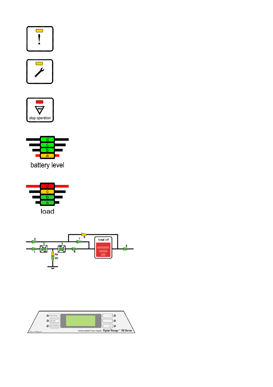
alarm
General alarm condition
It blinks when one or more alarm is activated. The internal buzzer is ON.
The LED remains lighted (with alarm condition still present) and the buzzer
stops as the key “mute” has been pressed.
service check
LED ON indicates that a regular maintenance service is needed.
May be reset by a service technician only.
See Section 11 – Maintenance.
The LED is ON also when the output switch Q1 is open, indicating that the
Inverter is in service mode, not supplying the load.
a)
LED ON indicates that the Battery reserve lasts for only 3 more minutes
(selectable).
b)
LED ON in case of overtemperature or overload >125% together with
missing Utility.
After the timeout the Inverter will shut down.
All LEDs ON indicate that the Battery is fully charged
LED a Yellow:
• Fixed: indicating
last
25 % of Battery backup.
• Blinking: indicating
Battery backup
≤
5%.
LED b, c, d Green:
• Each one indicating 25 % of Battery backup.
LEDs ON indicate the Load status of the UPS
LED d red (≥100 % load)
LED c yellow
(100%
load)
LED b green
(66%
load)
LED a green
(33%
load)
Fig. 5.2-1 LEDs on synoptic diagram
LEDs on synoptic diagram
LED 1
= Input Utility Rectifier (green)
LED 2
= Input Utility Bypass (green)
LED 3 =
Rectifier
ON
(green)
LED 4a = Discharging
(yellow)
LED 4b = Charging
(green)
LED 5
= Inverter ON (green)
LED 6
= Load on Inverter (green)
LED 7
= Load on Utility (green)
LED 8
= Output Load Voltage (green)
LED 9
= Manual Bypass (Q2) ON (yellow)
Fig. 5.2-2 LCD screen
User LCD Interface
Consist of an LCD screen, 4 lines with 20
characters each and six keys. It offers:
• UPS operating, AC and DC metering
information.
• History of events (alarms and messages).
• Functionality can be programmed to meet
customer needs by changing parameters.