GE Industrial Solutions HW006-010-012 Series User Manual
Page 19
Lineage Power
19
Data Sheet
June 26, 2009
36-75 Vdc Input; 1.2 Vdc to 5 Vdc Output; 6.6A to 12A
HW006/010/012 Series Power Modules; dc-dc Converters
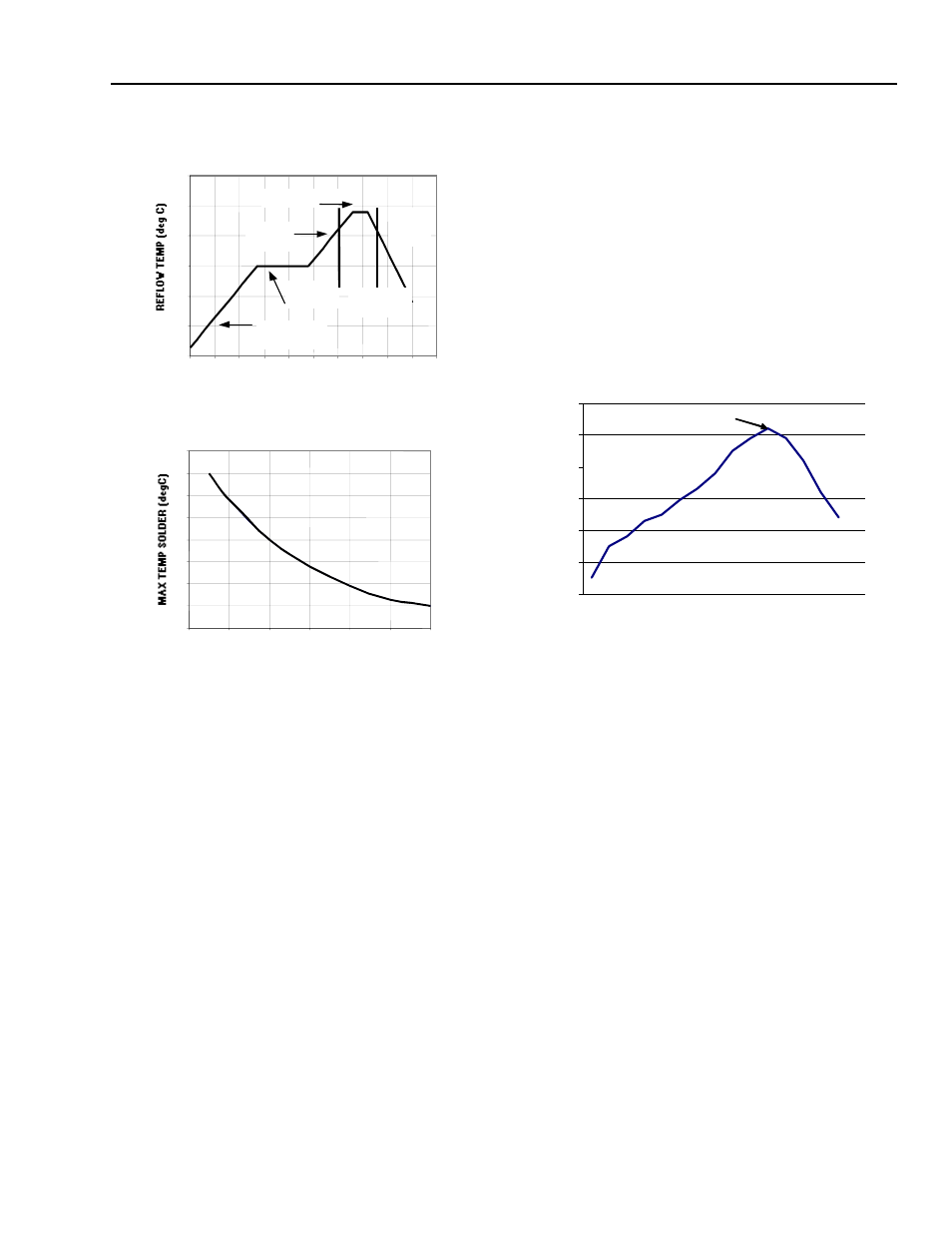
Figure 51. Recommended Reflow profile.
Figure 52. Time Limit curve above 205
0
C.
Lead Free Soldering
The -Z version SMT modules of the HW/HC series are lead-
free (Pb-free) and RoHS compliant and are compatible in a
Pb-free soldering process. Failure to observe the instructions
below may result in the failure of or cause damage to the
modules and can adversely affect long-term reliability.
Pb-free Reflow Profile
Power Systems will comply with J-STD-020 Rev. C (Moisture/
Reflow Sensitivity Classification for Nonhermetic Solid State
Surface Mount Devices) for both Pb-free solder profiles and
MSL classification procedures. This standard provides a rec-
ommended forced-air-convection reflow profile based on the
volume and thickness of the package (table 4-2). The sug-
gested Pb-free solder paste is Sn/Ag/Cu (SAC). The recom-
mended linear reflow profile using Sn/Ag/Cu solder is shown
in Figure. 53.
MSL Rating
The HW series SMT modules have a MSL rating of 1.
Storage and Handling
The recommended storage environment and handling proce-
dures for moisture-sensitive surface mount packages is
detailed in J-STD-033 Rev. A (Handling, Packing, Shipping
and Use of Moisture/Reflow Sensitive Surface Mount
Devices). Moisture barrier bags (MBB) with desiccant are
required for MSL ratings of 2 or greater. These sealed pack-
ages should not be broken until time of use. Once the origi-
nal package is broken, the floor life of the product at
conditions of < 30°C and 60% relative humidity varies accord-
ing to the MSL rating (see J-STD-033A). The shelf life for dry
packed SMT packages will be a minimum of 12 months from
the bag seal date, when stored at the following conditions: <
40° C, < 90% relative humidity.
Post Solder Cleaning and Drying Considerations
Post solder cleaning is usually the final circuit-board
assembly process prior to electrical board testing. The result
of inadequate cleaning and drying can affect both the
reliability of a power module and the testability of the finished
circuit-board assembly. For guidance on appropriate
soldering, cleaning and drying procedures, refer to Lineage
Power Board Mounted Power Modules: Soldering and
Cleaning Application Note (AP01-056EPS).
Figure 53. Recommended linear reflow profile using Sn/
Ag/Cu solder.
Solder Ball and Cleanliness Requirements
The open frame (no case or potting) power module will meet
the solder ball requirements per J-STD-001B. These require-
ments state that solder balls must neither be loose nor violate
the power module minimum electrical spacing.
The cleanliness designator of the open frame power module
is C00 (per J specification).
0
50
100
150
200
250
300
REFLOW TIME (S)
Preheat zone
max 4
o
Cs
-1
Soak zone
30-240s
Heat zone
max 4
o
Cs
-1
Peak Temp 235
o
C
Cooling
zone
1-4
o
Cs
-1
T
lim
above
205
o
C
200
205
210
215
220
225
230
235
240
0
10
20
30
40
50
60
TIME (S)
Per J-STD-020 Rev. C
0
50
100
150
200
250
300
Reflow Time (Seconds)
Re
fl
o
w
Te
m
p
(
°C
)
Heating
Zone
Peak Temp
* Min. Time
Above 235°C
*Time Above
217°C
Cooling
Zone