GE Industrial Solutions ZBTE Series User Manual
Page 9
Zenith ZTE/ZBTE Series Operation & Maintenance Manual
Page 7
91
R
-1000
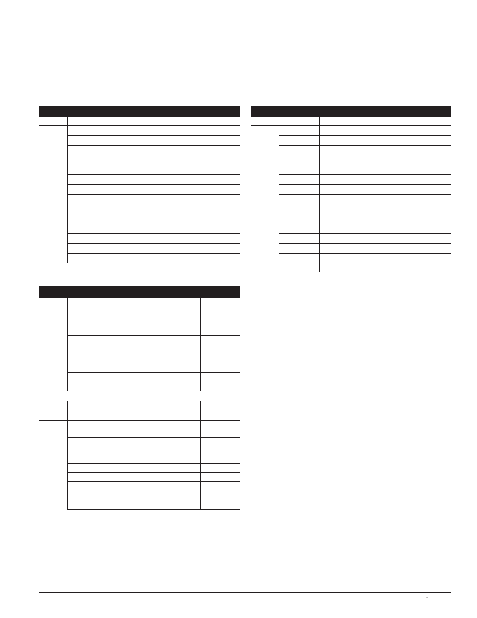
Figure 5
Example of Field Connection Diagram
Notes:
1. See Field connection wiring diagram for additional wiring details.
2. Controller inputs and outputs are field reconfigurable. “Factory Settings: indicate configuration at time of shipment.
3. From MX350 Display, go to \HOME\INPUTS or \HOME\OUTPUTS to see current configuration.
4. Record user configuration in “Field Setting” area below.
Name
Term #
Description
TB Strip
15
Connected to Source 1 (NO)
14
Connected to Source 1 (Common)
13
Connected to Source 1 (NO)
12
Connected to Source 1 (Common)
11
Connected to Source 2 (NO)
10
Connected to Source 2 (Common)
9
Connected to Source 2 (NO)
8
Connected to Source 2 (Common)
7
6
5
4
3
Engine Start – NC
2
Engine Start – Common
1
Engine Start – NO
G Input
Strip
G 7
Disconnect Switch (DS)
Factory Use
Only
G 8
Test with Load (Q2)
Factory Use
Only
G 9
Load Shed from S2 (R15)
Factory Use
Only
G 10
Bypass Xfer Time Delay to S1
G 11
Inhibit Xfer to S2 (Q3)
G 12
Inhibit Xfer to S1 (Q7)
G 13
Engine Start (SW1)
Com
+24VDC
Factory Use
Only
Name
Term #
Factory Setting
Field Setting
G Output
Strip
G 1 (NO/NC/
Common)
Load Shed from S2 (R15)
Factory Use
Only
G 2 (NO/NC/
Common)
Alternative Source Fail to Start
G 3 (NO/NC/
Common)
S1 Failure
G 4 (NO/NC/
Common)
S2 Failure to Connect
G 5 (NO/NC/
Common)
Load Control 1
Name
Term #
Description
TB Strip
12
Connected to Source 1 (NO)
11
Connected to Source 1 (Common)
10
Connected to Source 1 (NO)
9
Connected to Source 1 (Common)
8
Connected to Source 2 (NO)
7
Connected to Source 2 (Common)
6
Connected to Source 2 (NO)
5
Connected to Source 2 (Common)
4
Bypass in Source 1 (NO)
3
Bypass in Source 1 (Common)
2
Bypass in Source 2 (NO)
1
Bypass in Source 2 (Common)
3
Engine Start – NC
2
Engine Start – Common
1
Engine Start – NO
Non-Bypass ATS
Bypass ATS