GE Industrial Solutions ZBTE Series User Manual
Page 17
Zenith ZTE/ZBTE Series Operation & Maintenance Manual
Page 15
91
R
-1000
V
e
rt
ical
V
e
rt
ical
Horizontal
V
e
rt
ical
Horizontal
V
e
rt
ical
100-400A
600-1200A
1600-3000A
4000A
Swit
c
h P
o
sition
Swit
c
h P
o
sition
1.
Configuration
for
Aut
omatic
Operation
•
Manually operated Bypass Switch
contacts (BN/BE) ar
e open
•
A
TS is supplying load
•
Disconnect switch (DS) is in A
U
TO
•
Manually operated Bypass Switch contacts
(BN/BE) ar
e open
•
A
TS is supplying load
•
Disconnect switch (DS) is in A
U
TO
•
Manually operated Bypass Switch
contacts (BN/BE) ar
e open and A
TS
is supplying load
•
Disconnect Switch (DS) is in Auto
•
Manually operated Bypass Switch
contacts (BN/BE) ar
e open
•
A
TS is supplying load
•
Disconnect switch (DS) is in A
U
TO
2.
T
o
Bypass
AT
S
•
Open bottom cabinet door
•
Tu
rn Disconnect Switch (DS)
to INHIBIT
•
P
o
sition manual bypass handle (MBH)
to same power sour
ce at A
TS
•
Open bottom cabinet door
•
Tu
rn Disconnect Switch (DS) to INHIBIT
•
Tu
rn Bypass Selector Switch (BSS) to same
power sour
ce as A
TS
•
Tu
rn DS to Inhibit
•
Open Bypass Isolation Access panel
•
Tu
rn Bypass Selector Switch (BSS) to
same power sour
ce as A
TS
•
P
o
sition Manual Bypass Handle
(MBH) upw
ar
d
•
Open bottom cabinet door
•
Tu
rn Disconnect Switch (DS) to INHIBIT
•
P
o
sition manual bypass handle (MBH)
upw
ar
d
3.
To
Te
st
AT
S
•
Bypass per instruction #2 above
•
Move A
TS location handle (ALH)
to TEST location
•
Tu
rn DS to A
U
TO
•
Test switch (TS) on bottom
cabinet door will allow
electrical operation of A
TS
•
Bypass per instruction #2 above
•
Rotate crank mechanism counter
-clock
wise
until A
TS TEST light is illuminated
•
Tu
rn DS to A
U
TO
•
Test switch (TS) on bottom cabinet door
will allow electrical operation of A
TS
•
Bypass per above instructions
•
Rotate crank mechanism counter
-clock
-
wise until A
TS TEST light is illuminated
•
Tu
rn DS to Auto
•
Test Switch (TS) on micr
opr
ocessor
contr
oller will allow electrical
operation of A
TS
•
Bypass per instruction #2 above
•
Rotate crank mechanism counter
-clock-
wise until A
TS TEST light is illuminated
•
Tu
rn DS to A
U
TO
•
Test switch (TS) on bottom cabinet door
will allow electrical operation of A
TS
4.
T
o
Isolat
e
AT
S
•
Bypass per instruction #2 above
•
Move A
TS location handle (ALH)
to ISOL
A
TE position
•
Bypass per instruction #2 above
•
Rotate crank mechanism counter
-clock
wise
until A
TS ISOL
A
TED light is illuminated
(See Figur
e 15)
•
Bypass per above instructions
•
Rotate crank mechanism counter
-
clock
wise until A
TS
ISOL
A
TED light is illuminated
•
Bypass per instruction #2 above
•
Rotate crank mechanism counter
-
clock
wise until A
TS ISOL
A
TED light
is illuminated (See Figur
e 15)
5.
T
o
R
e
move
AT
S
•
Bypass per instruction #2
and isolate per #4 above
•
Move A
TS location handle (ALH)
to RELE
ASE position
•
Disconnect multipin plugs
•
Lift A
TS out of drawer
•
Bypass per instruction #2 and isolate per #4 above
•
Disconnect multipin plugs & external
connections to A
TS
•
Rotate four (4) power panel latches to ver
tical
position, slide A
TS for
w
a
rd
& lock mechanism
in place
•
Remove A
TS fr
om cabinet
•
Bypass and isolate per above
instructions
•
Open Automatic Transfer Switch
access panel
•
Slide four corner latches of A
TS to
innermost position
•
AT
S can now be r
emoved fr
om cabinet
•
Bypass per instruction #2 and isolate
per #4 above
•
Disconnect multipin plugs & external
connections to A
TS
•
Slide for (4) corner latches of A
TS to
innermost position
•
Remove A
TS fr
om cabinet
6.
To
R
e
connect
A
T
S Aft
e
r
R
emoval
•
Place A
TS into drawer slots
(fr
ont r
o
llers first)
•
Tu
rn Disconnect Switch (DS) to INHIBIT
•
Manually position A
TS into same
sour
ce as bypass switch
•
Reconnect multipin plugs & external
connections to A
TS
•
Push A
TS inw
a
rd
to engage carriage
•
Move A
TS location handle (ALH) to
TEST location (as indicated by light)
•
Tu
rn Disconnect Switch (DS) to
A
U
TO
& use T
est Switch (TS) to
electrically operate A
TS
•
Tu
rn Disconnect Switch (DS) to INHIBIT
•
Move A
TS location handle (ALH) to
A
U
TO
location
•
Tu
rn DS to A
U
TO
& open bypass
with MBH
•
A
TS is now f
u
lly automatic
•
Place A
TS in slide mechanism
•
Unlock slide mechanism
•
Slide A
TS over power panel latches &
rotate latches to horizontal position
•
Tu
rn Disconnect Switch (DS) to INHIBIT
•
Manually position A
TS into same sour
ce as
bypass switch
•
Reconnect multipin plugs & external
connections to A
TS
•
Rotate crank mechanism clock
wise until
A
TS TEST light is illuminated (See Figur
e 15)
•
Tu
rn Disconnect Switch (DS) to A
U
TO
& use
Test Switch (TS) to electrically operate A
TS
•
Tu
rn Disconnect Switch (DS) to INHIBIT
•
Rotate crank mechanism clock
wise until A
TS
location pointer is aligned with A
U
TO
mark on location
indicator
. (A
TS must be in same sour
ce as bypass)
•
Turn DS to A
U
TO
& open bypass with manual
bypass handle (MBH)
• A
TS is now f
u
lly automatic
•
Roll car
t back into cabinet
•
Slide four corner latches of
A
TS to outermost position
•
Tu
rn DS to Inhibit
•
Manually position A
TS into
same sour
ce as Bypass Switch
•
Close Automatic Transfer Switch
access panel
•
Rotate crank mechanism clock
wise
until A
TS T
est light is illuminated
•
Tu
rn DS to Auto and use TS to
electrically operate A
TS
•
Tu
rn DS to Inhibit
•
Rotate crank mechanism clock
wise
until A
TS location pointer is aligned
with Auto mark on location indicator
.
(A
TS must be in same sour
ce as Bypass)
•
Tu
rn DS to Auto and open
Bypass with MBH
•
A
TS is now f
u
lly automatic
•
Roll A
TS car
t back into cabinet
•
Slide four (4) corner latches of A
TS to
outermost position
•
Tu
rn Disconnect Switch (DS) to INHIBIT
•
Manually position A
TS into same sour
ce
as bypass switch
•
Reconnect multipin plugs & external
connections to A
TS
•
Rotate crank mechanism clock
wise until
A
TS TEST light is illuminated (See Figur
e 15)
•
Tu
rn Disconnect Switch (DS) to A
U
TO
& use
Test Switch (TS) to electrically operate A
TS
•
Tu
rn Disconnect Switch (DS) to INHIBIT
•
Rotate crank mechanism clock
wise until
A
TS location pointer is aligned with A
U
TO
mark on location indicator
. (A
TS must be
in same sour
ce as bypass)
•
Tu
rn DS to A
U
TO
& open bypass with
manual bypass handle (MBH)
•
A
TS is now f
u
lly automatic
7.
To
Operat
e
the Bypass
Swit
c
h When
the A
T
S is in
TEST or
ISOL
A
TE
•
Move the manual bypass
handle (MBH) to the av
ailable
power sour
ce
•
(1) Move manual bypass handle (MBH) downw
ar
d
to open the bypass power panel contacts,
•
(2) turn the bypass selector switch (BSS) to the
opposite power sour
ce, and
•
(3) move the MBH upw
ar
d to close into the
selected power sour
ce
•
(1) Move manual bypass handle
(MBH) downw
a
rd
to open the
bypass power panel contacts,
•
(2) turn the bypass selector switch (BSS)
to the opposite power sour
ce, and
•
(3) move the MBH upw
a
rd
to close
into the selected power sour
ce
•
(1) Move manual bypass handle (MBH)
downw
a
rd
to open the bypass power
panel contacts,
•
(2) turn the bypass selector switch (BSS)
to the opposite power sour
ce, and
•
(3) move the MBH upw
ar
d to close
into the selected power sour
ce
Not
es:
• Disconnect Switch (DS) in INHIBIT pr
events the electrical operation of the A
TS
.
• Do not use excessive for
ce on mechanical handles.
• Figur
es depict bypass operations r
e
lative to Sour
ce 1. Sequences ar
e the same for bypass operations r
e
lative to Sour
ce 2.
• When A
TS is in TEST or ISOL
A
TE, the bypass switch operates as a manual transfer switch to either av
ailable sour
ce, which is i
ndicated on the light panel. (See Figur
e 15)
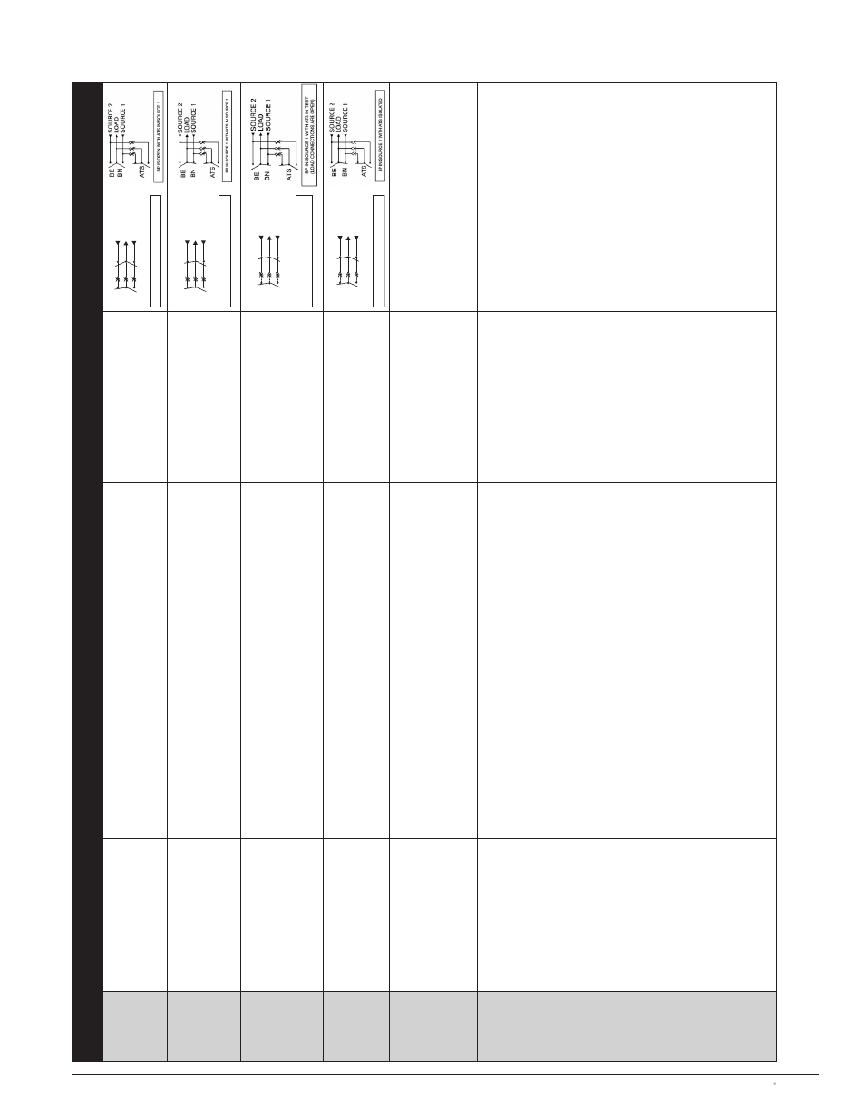
FIG. 1 BP IS OPEN WITH A
TS IN SOUR
CE 1
AT
S
BN
BE
SOUR
C
E 1
LOA
D
SOUR
C
E 2
FIG. 2 BP IN SOUR
CE 1 WITH A
TS IN SOUR
CE 1
AT
S
BN
BE
SOUR
C
E 1
LOA
D
SOUR
C
E 2
FIG. 3 BP IN SOUR
CE 1 WITH A
TS IN TEST
(L
O
AD C
O
NNECTIONS ARE OPEN)
AT
S
BN
BE
SOUR
C
E 1
LOA
D
SOUR
C
E 2
FIG. 4 BP IN SOUR
CE 1 WITH A
TS ISOL
A
TED
AT
S
BN
BE
SOUR
C
E 1
LOA
D
SOUR
C
E 2
Figure 16
Sequence of Operation for Bypass/Isolation Switches