Installation, Mounting, Inspection prior to initial energization – GE Industrial Solutions ZBTE Series User Manual
Page 4: Caution
91
R
-1000
Page 2
Zenith ZTE/ZBTE Series Operation & Maintenance Manual
Installation
When preparing to install the transfer switch, review the
documentation included with the unit. Each GE transfer
switch is factory wired and tested. A complete documen-
tation package is furnished with each switch, providing
descriptions and schematics for the following:
a. Standard and non-standard control interface
signals and options.
b. Sequence of operations.
c. Standard indicators, pushbuttons and annunciators.
d. Controller failure and return settings and time delays.
e. Description of the programmable engine exerciser.
f. Standard programmable control of switch operation.
g. User-configurable input and output.
h. System schematics:
1. Overall switch system.
2. Universal transformer assembly (UTA) power supply.
3. Transfer switch device layout.
4. Transfer switch power panel layout.
5. Interconnect plugs.
6. Customer connection wiring.
Mounting
Adequate lifting means must be used to mount the
transfer switch into place. The recommended method
for moving the ATS using lifting eyes, where supplied, and
a spreader bar is illustrated in Figure 1. Enough room
should be allowed to open the cabinet door(s) fully for
inspection and servicing of the switch per NEC and
local codes.
Inspection Prior to Initial Energization
Prior to energizing the transfer switch, perform the following:
1.
With a vacuum, remove any debris collected on
the switch during shipment or installation.
2.
Check engine start connections. The engine-start
terminals are located on terminal block positions
1 through 3 (see Figures 2 and 3). The E contact
provides the engine start signal from the automatic
transfer switch controller to the genset. The terminal
block has two sets of A3 (Source 2 position) normally
open contacts (NO) and two sets of A4 (Source 1
position) NO contacts.
3.
Verify the correct connection of all control wires.
4.
Check settings of all timers and adjust as necessary.
5.
Adjust any optional accessories as required.
6.
Verify that all Source 1, Source 2 and Load cables
are correctly connected to the clearly marked
terminals on the unit.
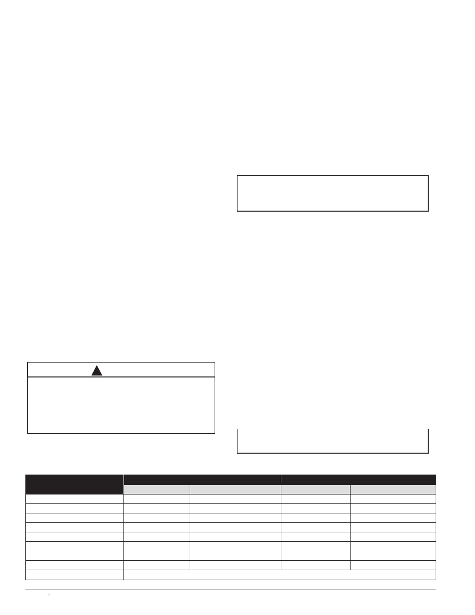
7.
Verify from Table 2 the number and sizes of cable
lugs, which are supplied as standard per the switch
amperage rating. Most transfer switches are sup-
plied with UL listed solderless screw-type terminals
as standard for the Source 1, Source 2 and Load
power connections.
8.
Verify equipment ground cable(s) are installed per
NEC and/or local codes.
9.
Verify that all cable lug connections are tightened
in accordance with torque values in Table 3.
10. Remove surface oxides from cables by cleaning
with a wire brush.
11. Make sure that all covers and barriers are installed
and properly fastened.
NOTE
Power panels ship from GE connected to Source 1.
NOTE
All control wires (18-12
AWG
) must be
torqued to 19 in/lbs (1.6 lb-ft) (2.2 N-m)
CAUTION
Before drilling conduit entry holes or any accessory mounting
holes, cover and protect the switch and control panel to
prevent dirt and metal fragments from entering the
mechanical and electrical components of the switch.
Failure to do so may result in damage and
malfunction of the switch and void the warranty.
!
Table 2
Power Connections: Screw Type Terminals for External Power Connections
Switch Size (Amps)
Source 1, Source 2 & Load Terminals
Neutral Bar (When Required)
Cable Per Pole
Range of Wire Sizes
No. of Cables per lug
Range of Wire Sizes
40
1
#8 AWG to 1/0
3
#8 AWG to 1/0
80
1
#8 AWG to 1/0
3
#8 AWG to 1/0
100
1
#8 AWG to 1/0
3
#8 AWG to 1/0
150
1
#8 AWG to 3/0
3
#8 AWG to 300 MCM
225
1
#6 AWG to 250 MCM
3
#6 AWG to 300 MCM
260, 400
1
#4 AWG to 600 MCM
3
#4 AWG to 300 MCM
600
2
#2 AWG to 600 MCM
8
#2 AWG to 600 MCM
800, 1000, 1200
4
#2 AWG to 600 MCM
12
#2 AWG to 600 MCM
1600, 2000, 3000, 4000
Line, Load and Neutral terminals are located in the rear of switch and arranged with bare bus bar