The control connections, Caution – GE Industrial Solutions ZBTE Series User Manual
Page 8
91
R
-1000
Page 6
Zenith ZTE/ZBTE Series Operation & Maintenance Manual
CHECKING THE SWITCH’S ABILITY TO TRANSFER
11. Turn the DS to AUTO position. This allows the MX350
controller to send a start signal to the generator.
12. Perform a System Test. The options available are
(a) Fast Test (test with load without time delays),
(b) Xfer Load and (c) No Xfer (test without load, gen-
erator start only). The test(s) can be initiated by the
green TEST button on the Graphical Control Panel.
13. After completing electrical tests, close and lock the
enclosure, including all small quarter-turn locks on
the enclosure door.
Electrical testing of the switch is further discussed in
the manual MX350 Automatic Transfer Control System
(Publication Number 1601-9071-A1).
The Control Connections
The ZTE and ZBTE lines of transfer switches are designed for
maximum flexibility and ease of installation. As illustrated in
Figure 2, the MX350 controller input/output and metering
modules, graphical control panel and power supplies
are mounted on the enclosure door. All terminal connec-
tions for the engine start, switch position contacts, input
and output relays are typically just inside the cabinet on
the right side for ease of accessibility. Configurable
input and output relays are PCB board mounted on DIN
rail in combinational arrays of 5 inputs and 7 outputs. A
“Field Connection Diagram” (see the example in Figure
5) is affixed on the cover of the universal transformer
assembly (
UTA
) power supply for easy reference. This
diagram provides the factory-supplied terminal board
connections as well as dry contact inputs and outputs
identified by terminal number as defined in the MX350
controller. The terminal board and I/O connections are
schematically shown in Figure 3. Close-up photographs
of an input and output PCB with terminal connections
are shown in Figures 6 and 7.
The number of PCB-mounted input and output relay
assemblies equals the number of “L cards” on the
microcontroller, more formally termed “IO_L modules.”
The assembly of output relays is GE part number 50P-3042.
The input relay assembly is GE part number 50P-3041. If
the microcontroller has one L card, then there will be
one pair of
GE P
art Number 50P-3041 and 50P-3042 PCB
combinations mounted on the DIN rail inside the enclosure.
For two L cards, there will be two sets of input and output
strips. The maximum combination is three pairs of I/O
strips (that is, a total of six relay DIN rail mounted PCBs).
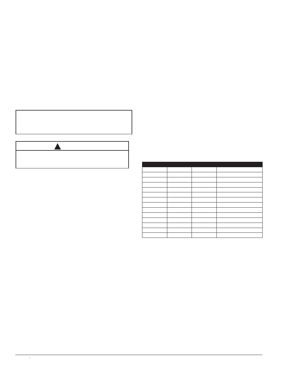
The controller automatically recognizes the physical
location of the input or output relays via an alpha-numeric
identification system. The first set of output relays are
named G1 through G5 while the input relays are identified
as G7 through G13. If a second L card exists in the micro-
controller, the second PCB-mounted assembly output relays
are named H1 through H5; the outputs are H7 through
H13. Similarly, a third IO_L module is related to inputs
I1 through I5 and outputs I7 through I13 (see Table 4).
CAUTION
Certain accessories, per specific schematics, can inhibit
automatic transfer. Engine Genset could start when engine
control wires are attached.
!
NOTE
A periodic test of the transfer switch under load conditions
is recommended to insure proper operation.
(See National Electric Code articles 700 and 701)
Terminal
Terminal
Terminal
Type
G1
H1
I1
Output
G2
H2
I2
Output
G3
H3
I3
Output
G4
H4
I4
Output
G5
H5
I5
Output
G6
H6
I6
Common for outputs
G7
H7
I7
Input
G8
H8
I8
Input
G9
H9
I9
Input
G10
H10
I10
Input
G11
H11
I11
Input
G12
H12
I12
Input
G13
H13
I13
Input
G14
H14
I14
Common for inputs
Table 4
IO_L Module Connections
Terminals G7 and G8 are always used for DS and Q2 functions, respectively, and cannot
be adjusted. Depending on the type of switch and features ordered, Terminals G1 through
G5 as well as G9 through G13 may not be available for customer configuration. See
electrical schematic.