The mx350 controller – GE Industrial Solutions ZBTE Series User Manual
Page 11
Zenith ZTE/ZBTE Series Operation & Maintenance Manual
Page 9
91
R
-1000
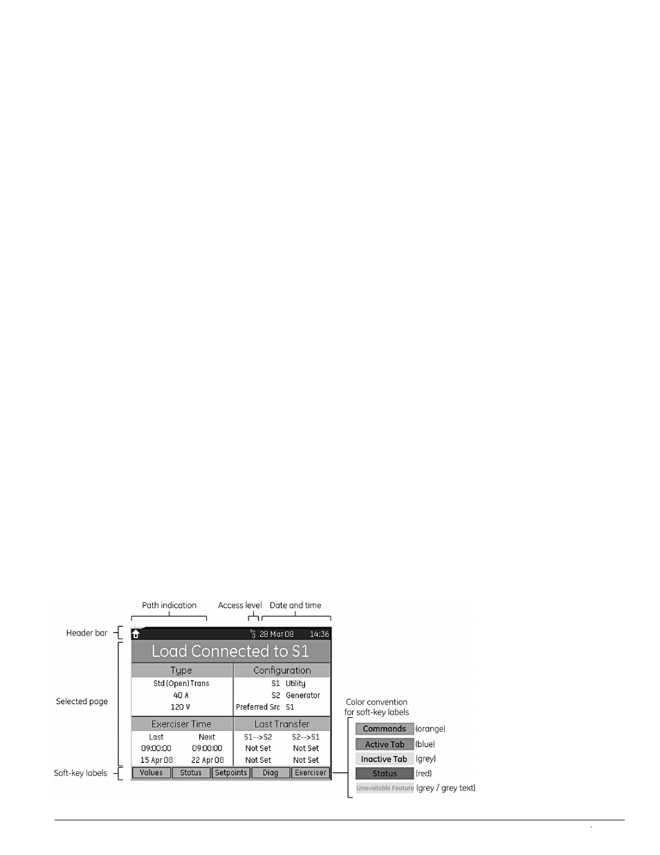
Figure 8
MX350 Graphical Display Components
The MX350 Controller
The MX350 microcontroller is a modular control and
monitoring system designed specifically for low-voltage
transfer switch applications. The MX350 provides the
following key benefits:
• Flexible control and communication options to suit
any low-voltage transfer switch application.
• Small footprint.
• Modular design, which reduces the number of spare
components for maintenance and testing.
• Integrated pushbuttons and LED indicators which
reduce required external components and wiring
• Multiple communication protocols which permit simple
integration into monitoring and control systems.
• A graphical control panel that provides local control
and access to system information.
Detailed technical information on the MX350 controller
is described in the manual MX350 Automatic Transfer
Control System (Publication Number 1601-9071-A1).
The MX350 Graphical Display and Keypad
The MX350 controller features a ¼
VGA
color graphical
display with status LEDs, an USB programming port and
menu-driven soft keys (see Figure 8) as well as dedicated
control and navigational keys. Each display page, in
turn, consists of three components: (1) a header bar,
(2) the selected page and (3) soft-key labels (Figure 8).
The header bar displays the hierarchical path name, the
date and time and the current password access level.
The soft-key labels are indicated on the bottom line.
Soft-keys are used for navigation, performing functions
and for acknowledgement transactions. Soft-keys labels
change to show relevant selections for the displayed
screen. The color of each soft-key label indicates its
functionality. Soft-keys are highlighted for the displayed
page, unauthorized keys are “greyed-out”, and unused
keys are not displayed.
The control panel LEDs summarize the status of the
transfer switch, including the following indications:
• ALARM: indicates that there is a problem with the ATS
or that a user configurable alarm condition is active.
• TD DELAY: indicates that the controller is timing before
taking the next control action.
• XFER INHIBIT: indicates that the controller will not
automatically transfer to the other source and that
operator intervention is required to allow transfer.
• S1 (Source 1) Available LED: indicates that S1 power
is present and within user defined limits.
• S2 (Source 2) Available LED: indicates that S2 power
is present and within user defined limits.
• S1 (Source 1) Status LED: indicates that the load is
connected to S1 power.
• S2 (Source 2) Status LED: indicates that the load is
connected to S2 power.
The MX350 controller page hierarchy is shown in Figure 9.
Operation Setpoints and
User-Configurable Inputs and Outputs
Operation setpoints define the acceptable electrical and
time limits for both Source 1 and Source 2. These set-
points define dropout and restore values for over and
undervoltage, over and under frequency, as well as the
associated time delays. Tables 7 and 8 provide typical
parameter settings for operation setpoints and timers.