Car0812fp series rectifier, Data sheet, Input: 85v – GE Industrial Solutions CAR0812FP series User Manual
Page 12: Output: 12v, Or 5 v, Control and read accuracy, Eeprom, Leds, Alarm table
GE
Data Sheet
CAR0812FP series rectifier
Input: 85V
AC
to 264V
AC
; Output: 12V
DC
@ 850W; 3.3V
DC
or 5 V
DC
@ 1A
May 2, 2013
©2013 General Electric Company. All rights reserved.
Page 12
Vin_UV_warn_limit (58):
This is another warning flag
indicating that the input voltage is decreasing dangerously
close to the low input voltage shutdown level.
Status_word (79):
returns two bytes of information. The
upper byte bit functionality is tabulated in the Status_word
section. The lower byte bit functionality is identical to
Status_byte.
Fan_speed (D7):
This register can be used to ‘read’ the fan
speed in adjustment percent (0 – 100%) or set the fan speed
in adjustment percent (0 – 100%). The speed of the fan
cannot be reduced below what the power supply requires
for its operation. The register value is the percent number, it
is not in linear format.
Invalid commands or data:
The power supply notifies the
MASTER if a non-supported command has been sent or
invalid data has been received. Notification is implemented
by setting the appropriate STATUS and ALARM registers and
setting the SMBAlert# flag.
Control and Read accuracy:
The estimates below are believed to be reasonable under
most operating conditions. However, these are typical
numbers and not hard bound values that cannot be
exceeded. In most nominal operating conditions the
returned values are significantly better than these
estimates.
Note that temperature measurements are accurate around
the shutdown limits and they get increasingly less accurate
as the temperature level decreases.
FUNCTION
ACCURACY
Vout_command ±
2%
Vout_OV_fault_limit ±
3%
Iout_OC_warn_limit
± 4% of FL
OT_warn_limit
± 5C
Vin_UV_warn_limit
± 3%
Vin_UV_fault_limit
± 3%
Read_Vin
± 3%
Read_Vout
± 2%
Read_Iout
± 4% of FL
Read_temperature
± 5C
EEPROM
The microcontroller has 96 bytes of EEPROM memory
available for the system host.
Another separate EEPROM IC will provide another 128 bytes
of memory with write protect feature. Minimum information
to be included in this separate EEPROM: model number,
revision, date code, serial number etc.
LEDs
Two LEDs are located on the front faceplate. The AC_OK LED
provides visual indication of the INPUT signal function. When the
LED is ON GREEN the power supply input is within normal design
limits.
The second LED DC/FLT is a tri-state LED. When GREEN there are no
faults and DC output is present. When AMBER a fault condition
exists but the power supply still provides output power. When RED
then a fault condition exists and the power supply does not provide
output power.
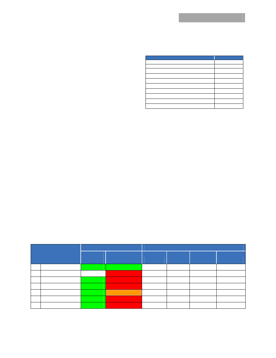
Alarm Table
Test Condition
LED Indicator
Monitoring Signals
LED1
AC
Tri-Color LED2
DC / FLT
FAULT
DC OK
INPUT OK
TEMP OK
1 Normal
Operation
Green
Green
High High High High
2
Low or NO INPUT
Off
Red
Low Low Low High
3 OVP
Green
Red
Low Low High High
4 Over
Current
Green
Red
Low Low High High
5
Temp Alarm Warning
Green
Orange
High
High High Low
6 Fault
Over
Temp
Green
Red
Low Low High Low
7 Remote
ON/OFF
Green
Red
Low Low High High
Notes: Test condition #2 had 2 modules plug in. One module is running and the other one is with no AC.