Af-60 lp™ micro drive programming guide, 3-4* accel/decel 1 – GE Industrial Solutions AF-60 LP Micro Drive User Manual
Page 28
[21]
Keypad Potentiometer
Use signals from Keypad potentiometer as reference.
3-17 Reference 3 Source
Option:
Function:
See Par. 3-15 for description.
[0]
No Function
No reference signal is defined.
[1]
Analog Input 53
Use signals from analog input 53 as reference.
[2]
Analog Input 60
Use signals from analog input 60 as reference.
[8]
Pulse input 33
Use signals from pulse input as reference, see par. 5-5*.
[11]
*
Local Bus Reference
Use signals from local bus as reference.
[21]
Keypad Potentiometer
Use signals from Keypad potentiometer as reference.
3-18 Relative Scaling Reference Source
Option:
Function:
Select the source for a variable value to be added to the fixed value defined in par. 3-14, Preset Relative Reference.
[0]
*
No Function
The function is disabled
[1]
Analog Input 53
Select analog input 53 as relative scaling reference source.
[2]
Analog Input 60
Select analog input 54 as relative scaling reference source.
[8]
Pulse Input 33
Select pulse input 33 as relative scaling reference source.
[11]
Local Bus Reference
Select local bus ref. as relative scaling reference source.
[21]
Keypad Potentiometer
Select Keypad potentiometer as relative scaling reference source.
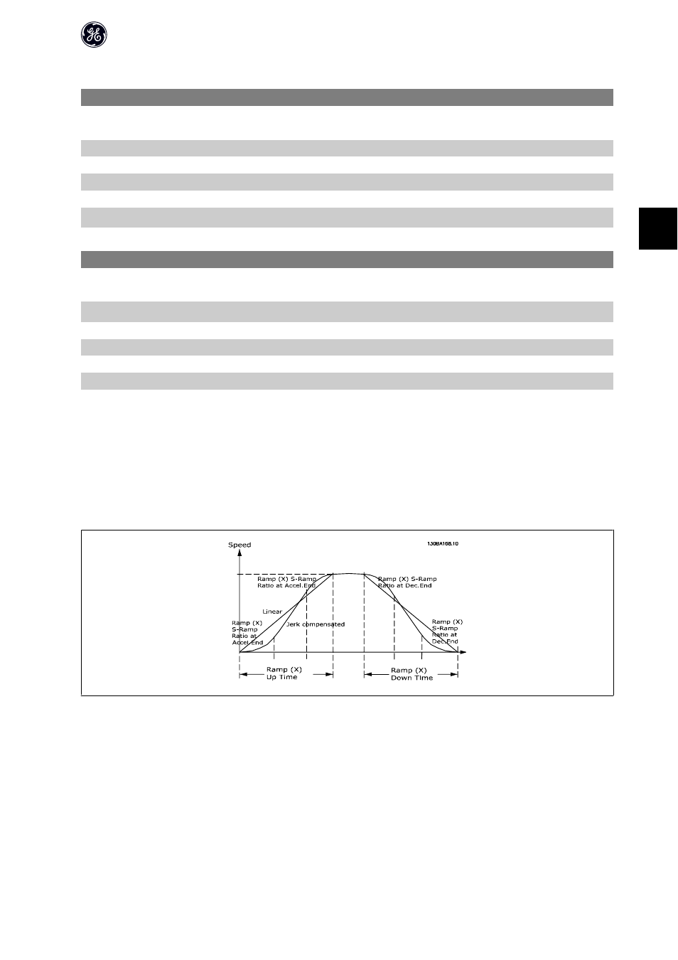
4.4.4. 3-4* Accel/Decel 1
A linear ramp is characterized by ramping up at a constant speed until the desired motor speed has been reached. Some overshoot may be experienced when
reaching speed, which may cause speed jerks for a short while before stabilizing.
An S-ramp accelerates more smoothly thus compensating for jerks when the speed is reached.
See the below figure for a comparison of the two ramp types.
Accel/Decel Time:
Acceleration time from 0 to nominal motor frequency (par. 1-23).
Ramp down: Deceleration time from nominal motor frequency (par. 1-23) to 0.
AF-60 LP™ Micro Drive Programming Guide
27
4