GE Industrial Solutions MicroVersaTrip Plus and MicroVersaTrip PM AK-1-15, AK-1-25 User Manual
Page 9
9
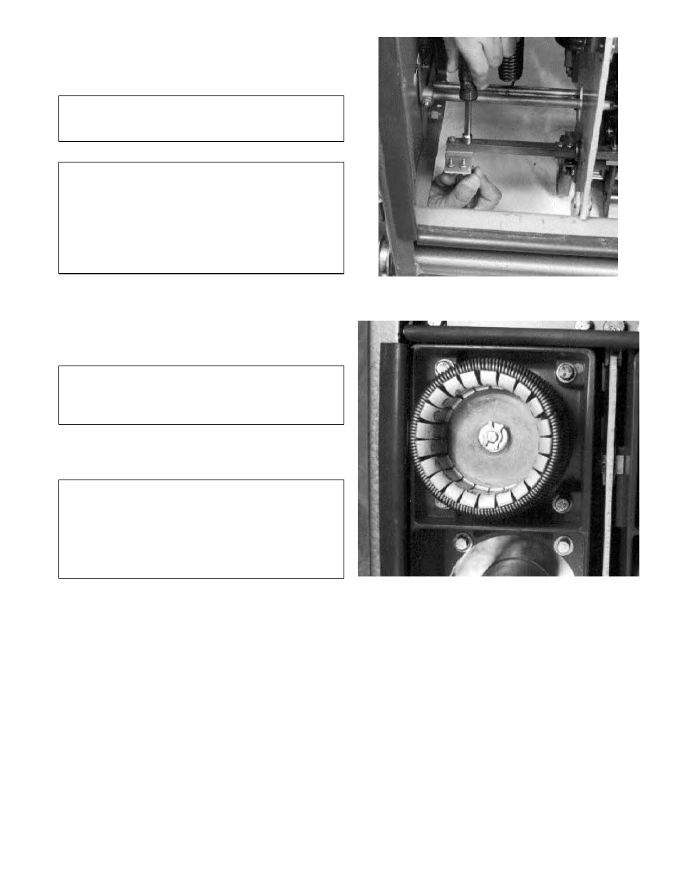
5. Remove the two mounting screws securing the
trip paddle for the right pole assembly to the
common trip shaft, as shown in Figure 15. Dis-
card the trip paddle and screws.
NOTE: Figure 15 shows the trip paddle from the
rear, with the right pole assembly removed from
the breaker.
WARNING: The mounting hardware used to reas-
semble the breaker’s pole assemblies must be cor-
rectly tightened for proper operation. Refer to the
original manufacturer’s operating and maintenance
manuals before performing the following step.
Failure to properly tighten the mounting hardware
may result in breaker failure, property damage,
and/or personal injury.
6. Reassemble each pole assembly to the breaker
by following steps 4 to 8 in Electromechanical
Trip Device Removal above in reverse order. Use
the X washer provided to reinstall the line-side
draw-out primary contact fingers, as shown in
Figure 16.
CAUTION: Seven X washers are supplied with the
conversion kit. One of the X washers in smaller than
the rest. Use the six larger washers for installing the
draw-out primary contact fingers.
7. Adjust the breaker’s contact wipe and gap set-
tings per the original manufacturer’s operating
and maintenance manuals.
WARNING: In order to ensure proper operation of
the breaker, it is crucial that the breaker’s contact
wipe and gap settings be adjusted per the original
manufacturer’s operating and maintenance manu-
als. Failure to properly adjust the contact assem-
blies will result in breaker failure, property damage,
and/or personal injury.
8. Reattach the three arc chutes to the breaker.
Continue back frame conversion with installation of
the phase sensors (CTs).
Figure 15. Removing the existing trip paddle, as seen from the
rear.
Figure 16. X washer installed on a draw-out contact finger
assembly.