Installing the flux shifter – GE Industrial Solutions MicroVersaTrip Plus and MicroVersaTrip PM AK-1-15, AK-1-25 User Manual
Page 14
14
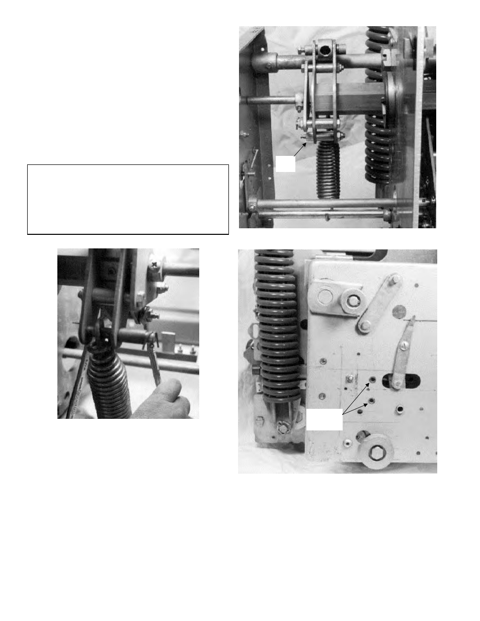
Installing the Flux Shifter
1. Remove and discard the existing hex-head bolt
and locking hex nut from the right-pole closing
arm, as shown in Figure 27.
2. Attach the reset stud to the right-pole closing
arm using the
5
/
16
-18 locking hex nut provided,
as shown in Figure 28. The hex-shaped end of
the reset stud should face toward the right side
of the breaker.
3. Mount the flux shifter assembly to the inside of
the breaker’s right side frame using the existing
holes, shown in Figure 29, and the two
1
/
4
-20 x
3
/
4
" screws, lock washers, and hex nuts provided,
as shown in Figure 30.
CAUTION: If the breaker contains a positive inter-
lock assembly on the right side frame, the mount-
ing eye bolt of the positive interlock’s spring must
be removed to allow installation of the flux shifter
assembly. After installation of the flux shifter, the
mounting eye bolt may be reinstalled in its original
location.
Figure 27. Removing the bolt and nut from the right-pole closing
arm assembly.
Figure 28. Reset stud installed on the right-pole closing arm.
Figure 29. Flux shifter mounting holes in the right side frame.
Reset
Stud
Flux Shifter
Mounting
Holes