GE Industrial Solutions MicroVersaTrip Plus and MicroVersaTrip PM AK-1-15, AK-1-25 User Manual
Page 11
11
4. Remove the retaining clip from the center
mounting post of each line and load draw-out
primary contact finger assembly, as shown in
Figure 20, then remove the fingers. Be sure to
save the existing flat washer from each assembly
for reuse, but discard the retaining clip.
5. Remove the three mounting screws on the exist-
ing current sensor triangular retaining plate on
each breaker pole. Remove and discard the
plates.
6. Remove and discard the existing current sensors,
trip actuator, trip device, trip device mounting
bracket, and CT wire harness from the breaker.
Refer to the original manufacturer’s operating
and maintenance manuals for details on
performing this step.
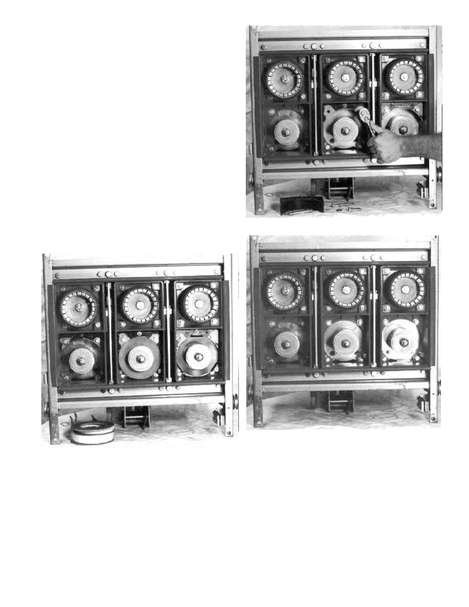
7. Remove the two mounting bolts on the existing
shunt on each pole of the breaker, as shown in
Figure 21, then remove and discard the shunt.
Replace the mounting hardware with the two
5
/
16
-18 x 1
3
/
4
" hex-head bolts, lock washers, and
flat washers provided, as shown in Figure 22.
Continue back frame conversion with installation of
the phase sensors (CTs).
Figure 20. Draw-out primary contact finger assembly removal.
Figure 21. Removing the shunt mounting bolts.
Figure 22. K-3000S with CTs and shunts removed.