GE Industrial Solutions MicroVersaTrip Plus and MicroVersaTrip PM AK-1-15, AK-1-25 User Manual
Page 8
8
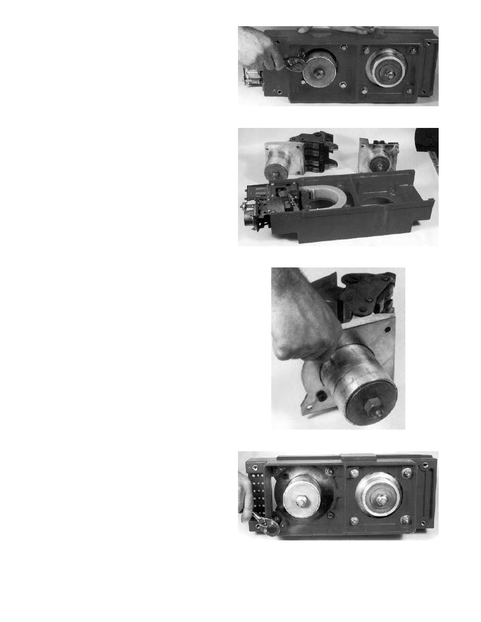
9. The stationary and moving contact assemblies
must be separated from the original molded base
assembly. Remove the eight hex-head mounting
bolts, as shown in Figure 11. Retain the four
mounting bolts from the stationary contact
assembly. Discard the four bolts for the moving
contact assembly and the original base molding
and electromechanical trip device. Figure 12
shows the disassembled pole unit.
10. If the existing insulating strips, shown in Figure
10, are made of fiber board, they must be
replaced. Remove and discard the old insulating
strips and replace with the new, slide-on
insulators provided in the kit.
Installing New Phase Base Moldings (K-
3000 and K-4000 only)
1. Mount the stationary contact assembly to the
new phase base molding provided using the
hardware removed earlier, as shown in Figure 14.
2. Attach the contact mounting plate to the moving
contact assembly with the two
5
/
16
-18 x
3
/
4
" flat-
head bolts provided, as shown in Figure 13. Prick
the contact mounting plate on either side of each
mounting bolt head with a center punch to lock
the mounting bolts in place. Repeat this step for
each phase of the breaker.
3. Install the moving contact assembly and mount-
ing plate on the phase base molding with the two
5
/
16
-18 x 1
3
/
4
" hex-head bolts, lock washers, and
flat washers provided, as shown in Figure 14.
Repeat this step for each phase of the breaker.
4. Attach the mounting plate to the phase base
molding with the two
5
/
16
-18 x 1
3
/
4
" hex-head
bolts, lock washers, flat washers, and hex nuts
provided, as shown in Figure 14. Repeat this step
for each phase of the breaker.
Figure 11. Removing the contact assembly mounting bolts.
Figure 12. Disassembled pole unit.
Figure 13. Installing the contact mounting plate.
Figure 14. Converted pole assembly.