Installing the trip unit bracket, Installing the wiring harness – GE Industrial Solutions MicroVersaTrip Plus and MicroVersaTrip PM AK-1-15, AK-1-25 User Manual
Page 19
19
Installing the Trip Unit Bracket
1. Secure the trip unit bracket assembly and the
auxiliary switch mounting plate to the breaker
with the three
1
/
4
-20 x
3
/
4
" screws, flat washers,
lock washers, and hex nuts provided, as shown
in Figure 39.
2. Attach the remaining mounting screws (removed
earlier) to the auxiliary switch mounting plate.
Installing the Wiring Harness
The wiring harness consists of a section for the trip
unit and another for communication. The communi-
cation harness is supplied with all kits, but may not
be required for MicroVersaTrip Plus™ trip units.
Separate and route the wiring harness as follows:
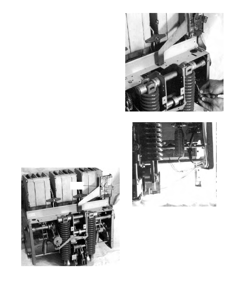
1. The four-pin flux shifter connector and the CT
wire leads should be routed through the wiring
hole in the auxiliary switch mounting plate or
just behind the mounting plate, as shown in Fig-
ure 39. The wiring harness should run along the
inside front edge of the breaker right side frame.
Connect the four-pin connector to its mating
connector on the flux shifter assembly. Tie the
harness away from any moving parts or sharp
edges, as shown in Figure 40.
2. Route the CT wires along the inside bottom edge
of the breaker right side frame toward each pole
assembly and connect to the mating lugs on the
phase sensors, as shown in Figure 41. Be sure to
observe proper polarity, with the white lead
connecting to the tap (X2) and the black lead to
common (X1).
Figure 39. Installing the trip unit bracket.
Figure 40. Flux shifter wiring harness leads.
Figure 41. CT wiring harness leads.
Trip Unit
Bracket