GE Industrial Solutions MicroVersaTrip Plus and MicroVersaTrip PM AK-1-15, AK-1-25 User Manual
Page 12
12
Installing the Phase Sensors (All Models)
1. Slide the CT spacer over each load-side copper
stab of the breaker, as illustrated in Figure 23.
2. Slide the phase sensors over each of the load-
side copper stabs. Be sure that each CT’s wire
leads are facing toward the front of the breaker
and are fed through the pole assembly under the
moving contact mounting plate, as shown in
Figure 24.
3. Mount the CT retaining plate to each phase base
molding using the two #10-32 x
1
/
2
" screws, lock
washers, and flat washers provided, as shown in
Figure 25. Be sure that the alignment stud on the
phase sensor inserts into the mating hole on the
CT retaining plate.
WARNING: In order to ensure the proper operation
of the phase sensors, it is crucial that the alignment
stud on each phase sensor aligns with the hole in
the CT retaining plate. Failure to properly install the
CTs may result in inadequate protection from the
trip unit.
4. Reattach the load-side draw-out primary contact
finger assemblies to the breaker using the pro-
vided X washers, as shown in Figure 16.
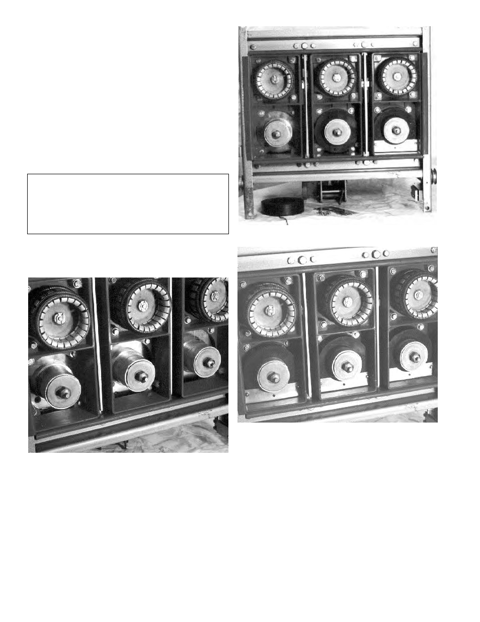
Figure 23. Installing the CT spacers.
Figure 24. Installing the phase sensors.
Figure 25. Installing the CT retaining plates.