Car1212dc series dc-dc converter, Data sheet, Input: -36v – GE Industrial Solutions CAR1212DC series User Manual
Page 12: Output: 12v, Or 5 v, Status register bit allocation, Command descriptions
GE
Data Sheet
CAR1212DC series DC-DC converter
Input: -36V
D C
to -75V
DC
; Output: 12V
DC
@ 1200W; 3.3V
DC
or 5 V
DC
@ 1A
October 21, 2013
©2013 General Electric Company. All rights reserved.
Page 12
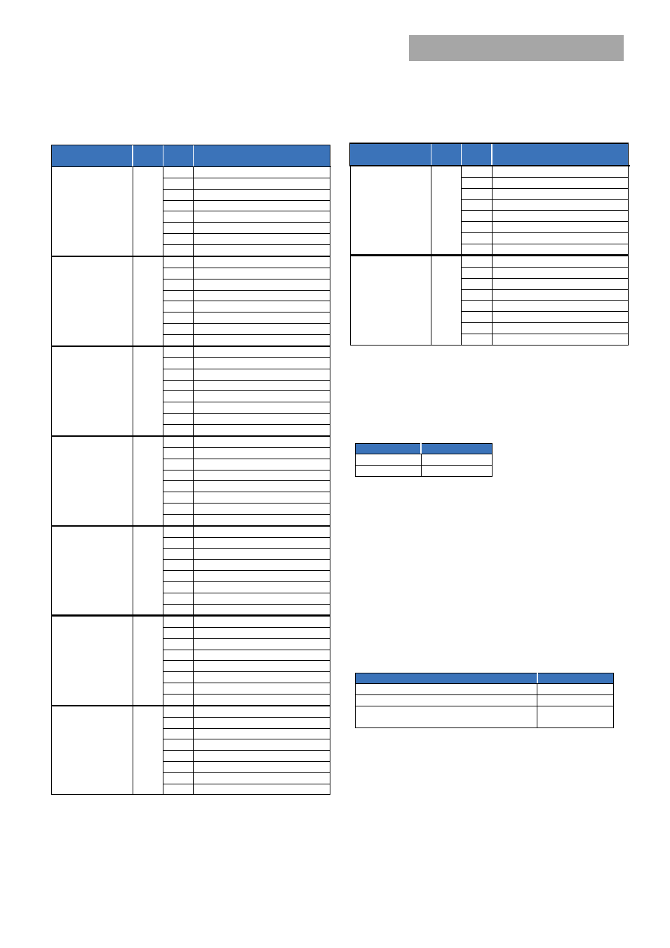
Status Register Bit Allocation:
Register
Hex
Code
Data
Byte
Function
Status_Byte
[ 0 – normal
1 – fault]
78
7
Busy
6
DC_ OFF
5
Output OV Fault
4
Output OC Fault
3
Input UV Fault
2
Temp Fault/warning
1
CML (communication fault)
0
None of Below
Status_word
(includes
Status_byte)
[ 0 – normal
1 – fault]
79
7
OV Fault/Warning detected
6
OC Fault/Warning detected
5
Input Fault/Warning
4
Mfr_specific register change
3
nPower_Good
2
Fan Fault or Warning
1
Other fault
0
Unknown
Status_Vout
[ 0 – normal
1 – fault]
7A
7
Vout OV Fault
6
Vout OV Warning
5
Vout UV Warning
4
Vout UV Fault
3
N/A
2
N/A
1
N/A
0
N/A
Status_Iout
[ 0 – normal
1 – fault]
7B
7
IOUT OC Fault
6
N/A
5
IOUT OC Warning
4
N/A
3
N/A
2
N/A
1
N/A
0
N/A
Status_input
[ 0 – normal
1 – fault]
7C
7
Vin OV Fault
6
Vin OV Warning
5
Vin UV Warning
4
Vin UV Fault
3
N/A
2
N/A
1
N/A
0
N/A
Status_temperature
[ 0 – normal
1 – fault]
7D
7
OT Fault
6
OT Warning
5
N/A
4
N/A
3
N/A
2
N/A
1
N/A
0
N /A
Status_cml
[ 0 – normal
1 – fault]
7E
7
Invalid/Unsupported Command
6
Invalid/Unsupported Data
5
Packet Error Check Failed
4
Memory Fault Detected
3
Processor Fault Detected
2
Reserved
1
Other Communications Fault
0
Other Memory or Logic Fault
Register
Hex
Code
Data
Byte
Function
Status_mfr_specific
[ 1 – normal
0 –fault]
80
7
3.3V_fault
6
OVSD
5
Interrupt
4
Fault detected
3
PS_remote_OFF
2
DC_fault
1
INPUT_fault
0
N/A
Status_fan_1_2
[ 0 – normal
1 – fault]
81
7
Fan 1 Fault
6
Fan 2 Fault
5
N/A
4
N/A
3
Fan 1 Speed Overridden
2
Fan 2 Speed Overridden
1
N/A
0
N/A
Command Descriptions
Operation (01) :
By default the Power supply is turned ON at power
up as long as Power ON/OFF signal pin is active HI. The Operation
command is used to turn the Power Supply ON or OFF via the
PMBus. The data byte below follows the OPERATION command.
FUNCTION
DATA BYTE
Unit ON
80
Unit OFF
00
To RESET the power supply cycle the power supply OFF, wait at
least 2 seconds, and then turn back ON. All alarms and shutdowns
are cleared during a restart.
Clear_faults (03):
This command clears all STATUS and FAULT
registers and resets the SMBAlert# line.
If a fault still persists after the issuance of the clear_faults
command the specific registers indicating the fault are reset and
the SMBAlert# line is activated again.
WRITE_PROTECT register (10):
Used to control writing to the PMBus
device. The intent of this command is to provide protection against
accidental changes. All supported command parameters may have
their parameters read, regardless of the write_protect settings. The
contents of this register can be stored to non-volatile memory using
the Store_default_code command. The default setting of this
register is disable_all_writes except write_protect 0x80h. This
default cannot be changed.
FUNCTION
DATA BYTE
Enable all writes
00
Disable all writes except write_protect
80
Disable all writes except write_protect and
OPERATION
Vout_Command (21) :
This command is used to change the output
voltage of the power supply. Changing the output voltage should be
performed simultaneously to all power supplies operating in parallel
using the Global Address (Broadcast) feature. If only a single power
supply is instructed to change its output, it may attempt to source
all the required power which can cause either a power limit or
shutdown condition.
Software programming of output voltage permanently overrides
the set point voltage configured by the Vprog signal pin. The
program no longer looks at the ‘Vprog pin’ and will not respond to
any hardware voltage settings. If power is removed from the
µController it will reset itself into its default configuration looking at
the Vprog signal for output voltage control. In many applications,