Receiving a clear_faults command, Execution of a read of the status_word register, Pmbustm commands – GE Industrial Solutions CAR1212DC series User Manual
Page 10: Car1212dc series dc-dc converter, Data sheet, Input: -36v, Output: 12v, Or 5 v, Digital feature descriptions, Pmbus
GE
Data Sheet
CAR1212DC series DC-DC converter
Input: -36V
D C
to -75V
DC
; Output: 12V
DC
@ 1200W; 3.3V
DC
or 5 V
DC
@ 1A
October 21, 2013
©2013 General Electric Company. All rights reserved.
Page 10
Digital Feature Descriptions
PMBus™ compliance:
The power supply is fully compliant to the
Power Management Bus (PMBus™) rev1.2 requirements.
Manufacturer specific commands located between addresses 0xD0
to 0xEF provide instructions that either do not exist in the general
PMBus specification or make the communication interface simpler
and more efficient.
Master/Slave:
The ‘host controller’ is always the MASTER. Power
supplies are always SLAVES. SLAVES cannot initiate
communications or toggle the Clock. SLAVES also must respond
expeditiously at the command of the MASTER as required by the
clock pulses generated by the MASTER.
Clock stretching:
The ‘slave’ µController inside the power supply
may initiate clock stretching if it is busy and it desires to delay the
initiation of any further communications. During the clock stretch
the ‘slave’ may keep the clock LO until it is ready to receive further
instructions from the host controller. The maximum clock stretch
interval is 25ms.
The host controller needs to recognize this clock stretching, and
refrain from issuing the next clock signal, until the clock line is
released, or it needs to delay the next clock pulse beyond the clock
stretch interval of the power supply.
Note that clock stretching can only be performed after completion
of transmission of the 9
th
ACK bit, the exception being the START
command.
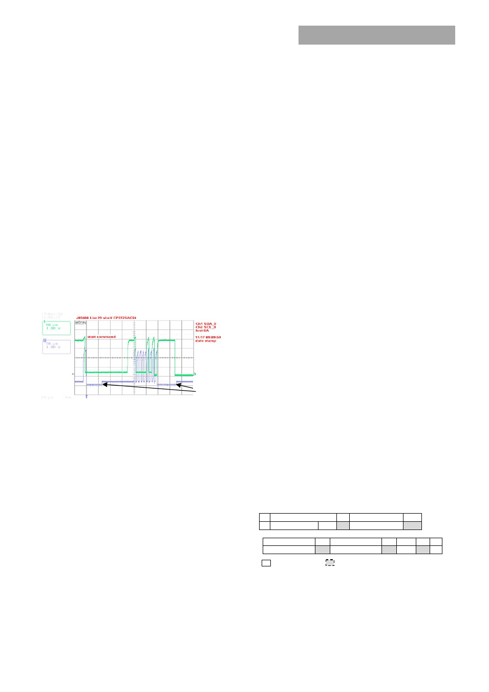
Figure 13. Example waveforms showing clock stretching.
I
²C Bus Lock-Up detection:
The device will abort any transaction
and drop off the bus if it detects the bus being held low for more
than 35ms.
Communications speed:
Both 100kHz and 400kHz clock rates are
supported. The power supplies default to the 100kHz clock rate. The
minimum clock speed specified by SMBus is 10 kHz.
Packet Error Checking (PEC):
Although the power supply will
respond to commands with or without the trailing PEC, it is highly
recommended that PEC be used in all communications. The
integrity of communications is compromised if packet error
correction is not employed. There are many functional features,
including turning OFF the main output, that should require
validation to ensure that the correct command is executed.
PEC is a CRC-8 error-checking byte, based on the polynomial C(x) =
x
8
+ x
2
+ x + 1, in compliance with PMBus™ requirements. The
calculation is based in all message bytes, including the originating
write address and command bytes preceding read instructions. The
PEC is appended to the message by the device that supplied the last
byte.
SMBAlert#
:
The µC driven SMBAlert# signal informs the
‘master/host’ controller that either a STATE or ALARM change has
occurred. Normally this signal is HI. The signal will change to its LO
level if the power supply has changed states and the signal will be
latched LO until the power supply either receives a ‘clear’ instruction
as outlined below or executes a READ STATUS_WORD. If the alarm
state is still present after the STATUS registers were reset, then the
signal will revert back into its LO state again and will latch until a
subsequent reset signal is received from the host controller.
The signal will be triggered for any state change, including the
following conditions;
•
VIN and under or over voltage
•
IOUT over current
•
Over Temperature warning or fault
•
Fan Failure
•
Communication error
•
PEC error
•
Invalid command
•
Internal faults
The power supply will clear the SMBusAlert# signal (release the
signal to its HI state) upon the following events:
•
Receiving a CLEAR_FAULTS command
•
The main output recycled (turned OFF and then ON) via the
ENABLE signal pin
•
The main output recycled (turned OFF and then ON) by the
OPERATION command
•
Execution of a READ of the STATUS_WORD register
Global broadcast:
This is a powerful command because it can
instruct all power supplies to respond simultaneously in one
command. But it does have a serious disadvantage. Only a single
power supply needs to pull down the ninth acknowledge bit. To be
certain that each power supply responded to the global instruction,
a READ instruction should be executed to each power supply to
verify that the command properly executed. The GLOBAL
BROADCAST command should only be executed for write
instructions to slave devices.
Read back delay:
The power supply issues the SMBAlert #
notification as soon as the first state change occurred.
During an
event a number of different states can be transitioned to before the
final event occurs. If a read back is implemented rapidly by the host
a successive SMBAlert# could be triggered by the transitioning state
of the power supply. In order to avoid the triggering of successive
SMBAlert# s and thus reading a transitioning state, it is prudent to
wait more than 2 seconds after the receipt of an SMBAlert# before
executing a read back. This delay will ensure that only the final state
of the power supply is captured.
Successive read backs:
Successive read backs to the power supply
should not be attempted at intervals faster than every one second.
This time interval is sufficient for the internal processors to update
their data base so that successive reads provide fresh data.
PMBus
TM
Commands
Standard instruction:
Up to two bytes of data may follow an
instruction depending on the required data content. Analog data is
always transmitted as LSB followed by MSB. PEC is optional and
includes the address and data fields.
1
8
1
8
1
S Slave address
Wr A Command Code
A
8
1
8
1
8
1 1
Low data byte
A
High data byte
A
PEC A
P
Master to Slave Slave to Master
SMBUS annotations; S – Start , Wr – Write, Sr – re-Start, Rd –
Read, A – Acknowledge, NA – not-acknowledged, P – Stop
Clock
Stretch