Surface mount information, Austin lynx – GE Industrial Solutions Austin Lynx 24V User Manual
Page 18
Data Sheet
September 10, 2013
Austin Lynx
TM
24V: Non-isolated Power Modules:
18/20– 30/32Vdc input; 3 – 6Vdc & 5 – 15Vdc Output; 30/50W
LINEAGE
POWER
18
Surface Mount Information
(continued)
Lead Free Soldering
The –Z version Austin Lynx 24V SMT modules are
lead-free (Pb-free) and RoHS compliant and are both
forward and backward compatible in a Pb-free and a
SnPb soldering process. Failure to observe the
instructions below may result in the failure of or cause
damage to the modules and can adversely affect
long-term reliability.
Pb-free Reflow Profile
Power Systems will comply with J-STD-020 Rev. C
(Moisture/Reflow Sensitivity Classification for
Nonhermetic Solid State Surface Mount Devices) for
both Pb-free solder profiles and MSL classification
procedures. This standard provides a recommended
forced-air-convection reflow profile based on the
volume and thickness of the package (table 4-2). The
suggested Pb-free solder paste is Sn/Ag/Cu (SAC).
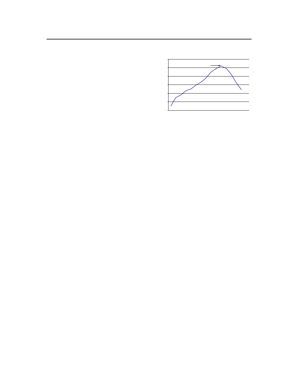
The recommended linear reflow profile using
Sn/Ag/Cu solder is shown in Figure. 37.
MSL Rating
The Austin Lynx 24V SMT modules have an MSL
rating of 2a.
Storage and Handling
The recommended storage environment and handling
procedures for moisture-sensitive surface mount
packages is detailed in J-STD-033 Rev. A (Handling,
Packing, Shipping and Use of Moisture/Reflow
Sensitive Surface Mount Devices). Moisture barrier
bags (MBB) with desiccant are required for MSL
ratings of 2 or greater. These sealed packages
should not be broken until time of use. Once the
original package is broken, the floor life of the product
at conditions of
≤ 30°C and 60% relative humidity
varies according to the MSL rating (see J-STD-033A).
The shelf life for dry packed SMT packages will be a
minimum of 12 months from the bag seal date, when
stored at the following conditions: < 40° C, < 90%
relative humidity.
Post Solder Cleaning and Drying
Considerations
Post solder cleaning is usually the final circuit-board
assembly process prior to electrical board testing. The
result of inadequate cleaning and drying can affect
both the reliability of a power module and the
testability of the finished circuit-board assembly. For
guidance on appropriate soldering, cleaning and
drying procedures, refer to Board Mounted Power
Modules: Soldering and Cleaning Application Note
(AN04-001).
Per J-STD-020 Rev. C
0
50
100
150
200
250
300
Reflow Time (Seconds)
R
efl
ow
T
em
p
(°
C
)
Heating Zone
1°C/Second
Peak Temp 260°C
* Min. Time Above 235°C
15 Seconds
*Time Above 217°C
60 Seconds
Cooling
Zone
Figure 37. Recommended linear reflow profile
using Sn/Ag/Cu solder.