Ocean Optics Jaz Install User Manual
Page 48
5: Operating the JAZ-INDY Module
40
013-RD000-000-02-201103
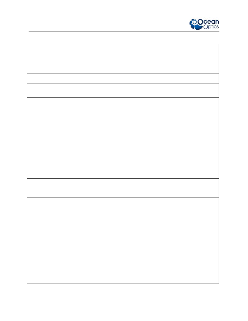
Menu Tree Description
Menu Item
Description
Configure
Enables you to manually set options for the device.
GPIO
Contains parameters for the 8 GPIO lines.
Set Direction
Sets the operational direction for each of the GPIO lines to input or output.
Set Output
Values
If any GPIO lines are set to output, this menu item appears to allow you to set the
output value for each output GPIO to 0 (low) or 1.
Analog V Out
Allows you to change each of the 4 voltage output settings from -5Vdc to +5Vdc.
Change the voltage value using the * (left)/ # (right) buttons. Change the -/+ sign
using the
▲ (Up)/ ● (Down) buttons, then press √ to accept your selection.
4-20mA
Excitation
This selection affects the output of the 4-20mA current loop receiver. Select Enable
for the receiver to provide a voltage source for an external 4-20mA current loop. You
can choose to provide a 10Vdc or 20Vdc voltage.
4-20mA Tx
Control
Provides control of the 4-20mA current loop transmitter to source 4 – 20 mA into the
current loop. Control the value by adjusting the percentage of current flowing into the
current loop using the 4-20mA Tx% setting (0 – 100%). Use the
▲ (Up)/ ● (Down)
buttons to select the desired value, then press
√ to accept your selection.
NOTE: This menu option will display only if an excitation voltage is connected to the
4-20mA current loop transmitter.
Monitor Inputs
Enables you to monitor the status of the Analog V, Analog Current and Digital inputs.
Analog V
Select Analog V to monitor the four Analog-to-Digital input voltages (for channels 1,
2, 3 and 4), including the two differential readings. The two differential readings are
taken by subtracting Channel 1 from Channel 2, and Channel 3 from Channel 4.
Analog Current
Displays the amount of current in the JAZ-Indy module’s 4-20mA receiver circuit.
The values shown are:
Current in mA,
Percentage of 4-20mA value (0 –100%), with 0% = 4mA and 100% = 20mA.
If current dips below 4mA, < appears next to the value. If current rises above
20mA, > appears. The percentage value will never display for input current
below 4 mA or above 20 mA.
Count is the digital value collected at the current-sense input of the Analog-
to-Digital converter (Channel 7).
Digital
When enabled, the Digital Inputs sub menu shows the state of the GPIO lines
configured as inputs:
↑ indicates a TTL high input (Logic 1)
↓ indicates a TTL low input (Logic 0)
NOTE: Arrows are not shown for bits assigned as outputs.